Continue to Site

Welcome to our site!

Electro Tech is an online community (with over 170,000 members) who enjoy talking about and building electronic circuits, projects and gadgets. To participate you need to register. Registration is free. Click here to register now.

  • Welcome to our site! Electro Tech is an online community (with over 170,000 members) who enjoy talking about and building electronic circuits, projects and gadgets. To participate you need to register. Registration is free. Click here to register now.

conventions in solving circuit

Status
Not open for further replies.

tintincute

New Member
hi

i would like to ask if there are rules on how to solve circuits involving their signs. i have a circuit here and quite confuse with their (-) and (+) flow. are there basis for that?
please see attachment.
My solutions are the following:

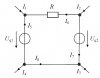
Compute the I4, I5, I6, I7, and I8
Given are the ff:
Eq1 = 240 V
Eq2 = 120 V
I1 = 10 A
I2 = 20 A
I3 = 30 A

Steps:
Er + E1 - E2 = 0

My question is why should I minus E2 here? i see that the directions of both voltages are the same.
there must be a reason and i can't remember anymore.

thanks for your help in advance!

regards

note: Er here is the voltage flowing R=100 and I6 the direction is going to the left <----------
 

Attachments

  • circuit.jpg
    circuit.jpg
    44.5 KB · Views: 161
If you have an idea which way the currents flow then draw them the way you think, otherwise just draw them anyway.

If the arrow is pointing in the wrong direction, when you do the maths the value of the current will be -ve.
No problem, just know that the current flows the opposite way from what your arrow shows.

JimB
 
Er + E1 has to equal E2, so Er + E1 -E2 = 0, yes?
 
Last edited:
Hello,


There are two conventions accepted for the direction of current flow.

One is usually called "conventional" current flow, and the other
is called "electron" current flow. They go by other names too.

Conventional current flow is from the positive terminal of the voltage
source, through the circuit, and finally back to the negative terminal.
Electron current flow is just the opposite.

The current arrows with conventional current flow are drawn to
indicate the direction of current, which is from the positive source
terminal through the circuit to the negative terminal of the source.

Here's an example:
Code:
 --->-----
|         |
|         |
+         |
E         R1
-         |
|         |
|         |
 ---------

The arrow shows conventional current flow.
E is a battery, R1 is a resistor.
 
Last edited:
this is still quite confusing. not really sure what's the basis.

The voltage drops or rises around a loop have to equal zero.
Since the wires shown in your diagram have zero resistance the only rises are due to the two voltage sources and the only drop is across the resistor. If the voltage sources add then it's 120 + 240 = 360, otherwise it's 240-120 = 120.
This 360 or 120 must be dropped across the resistor.
 
Your diagram makes me nuts. I hope I never see another one like this.

If you assume that the wire carrying I8 is a single node, then I4 is in parallel with I3. The voltage sources look like a short to the current sources, so the resistor is shorted out, so now you have I1 + I2 = I3 + I4, so I4 must be zero, so open the line carrying I4.

Notice that I1, I5 and I6 are all going into the same node. This is impossible, so the sign of one of these currents is wrong.

Since I4 = 0, I5 = I8.
Since the voltage of Uq1>the voltage of Uq2, I think I8 is the correct direction of current so the I5 arrow should be reversed. This doesn't seem to contradict anything so far. Delete the I5 notation from the drawing.

So,
I8 = I1 + I6
I8 = I3 + I7
I6 = I2 + I7

I1 = 10A
I2 = 20A
I3 = 30A

I couldn't solve this in closed form so I put it into a spreadsheet and plugged in numbers for I7.
When I plugged in 1A for I7, I8 said 31A, 31A and I6 said 21A.
With I7 at 100A, I8 said 130A, 31A and I6 said 120A.
The I1-I3 totals always worked.

I think I7 is indeterminate without knowing the value of R. It is a circulating current and is due to the voltage sources and the resistor.

I think the Uq1, Uq2, R circuit counts as a single node for the purposes of I1-I3.

Somewhere in all this is the answer to your question, I hope.
 
Last edited:
Status
Not open for further replies.

New Articles From Microcontroller Tips

Back
Top