Hello,
I'm working on an automation system for my hobby model train system, n-scale.
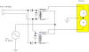
I have developed a Arduino based circuit that uses IR sensors and shift registers to detect train position and then uses an h-bridge circuit to send forward/reverse DC power to throw track switches (turnouts) to divert the train down one track or another based on the Arduino programming.
My issue that I want to solve involves some of the track switches which are actually AC based, 3 wire electric switches. I'm not sure how to integrate these into my DC based system.
I know you don't know anything of my system, but at its basics, I can control numerous sets (pairs) of DC +/- wires going to each of the DC switches/turnouts, and I can reverse the DC polarity on those pairs of wires so as to throw a switch in forward or reverse.
Now the AC switches are 3 wired. Here is a link to a installation instruction picture which will give a good understand of how they are wired; mine are just like this. The real information is the wiring diagram at the bottom.
http://www.nscalesupply.com/atl/ATL-65.html
The control switches are those buttons on the "switch control box", which are sliders, left/right and press to activate the power. So the slider buttons are control direction. You'll notice they are powered from the AC power pack via 2 wires.
This further confuses me because I thought AC was "alternating" current, so I didn't think a motor could be made to spin opposite direction by flipping the wires around, like a DC circuit would.
Nevertheless ... how might I deal with these 3-wire AC switches in my DC based system, which uses h-bridge design to reverse DC power?
Ideally I would like to just expand on my DC h-bridge controlled DC power and send that to the AC switches. Might this work if wired properly?
How would 2-wire DC be wired to those 3-wire AC switches?
Thanks for reading, and looking forward to any input or comments.
Cheers,
Eric
I'm working on an automation system for my hobby model train system, n-scale.
I have developed a Arduino based circuit that uses IR sensors and shift registers to detect train position and then uses an h-bridge circuit to send forward/reverse DC power to throw track switches (turnouts) to divert the train down one track or another based on the Arduino programming.
My issue that I want to solve involves some of the track switches which are actually AC based, 3 wire electric switches. I'm not sure how to integrate these into my DC based system.
I know you don't know anything of my system, but at its basics, I can control numerous sets (pairs) of DC +/- wires going to each of the DC switches/turnouts, and I can reverse the DC polarity on those pairs of wires so as to throw a switch in forward or reverse.
Now the AC switches are 3 wired. Here is a link to a installation instruction picture which will give a good understand of how they are wired; mine are just like this. The real information is the wiring diagram at the bottom.
http://www.nscalesupply.com/atl/ATL-65.html
The control switches are those buttons on the "switch control box", which are sliders, left/right and press to activate the power. So the slider buttons are control direction. You'll notice they are powered from the AC power pack via 2 wires.
This further confuses me because I thought AC was "alternating" current, so I didn't think a motor could be made to spin opposite direction by flipping the wires around, like a DC circuit would.
Nevertheless ... how might I deal with these 3-wire AC switches in my DC based system, which uses h-bridge design to reverse DC power?
Ideally I would like to just expand on my DC h-bridge controlled DC power and send that to the AC switches. Might this work if wired properly?
How would 2-wire DC be wired to those 3-wire AC switches?
Thanks for reading, and looking forward to any input or comments.
Cheers,
Eric
")