Hello,
I'm working on a small project at home and want to see if anyone can give me some ideas. I'm trying to build a circuit to control a 24VDC Brushless Fan with PWM signal from a PIC18F4520, the fan draws 1A of current at full speed.
I'm in the processes of designing the circuit and have done some testing. One of the things is that I'm not sure at what frequency I should have my PWM set for, I've seen most designs use something in the range of 22KHz to 30KHz, (what determines this, the fan?).
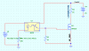
So my idea is to isolate the pic from the fan using an opto-isolator (4N32). I've done some work with optos in the past, but have forgotten much about it and the same goes with the MOSFET to drive the FAN.
Basically in the circuit below I'm having difficulty calculating (theoretically) what the output (Gate) to the MOSFET is going to be for a given CTR. I've always been confused with this and want to be able to get over with it. Next what voltage do I need to drive the gate of the mosfet, I know this depends on the drain current, but like on the opto-isolator I've forgotten how to do all the math. Some input or directions will be appreciated. I'm using R4 to simulate the fan, I don't have a protection diode because the Fan has internal protection already.
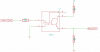
In reality I have a 4N32 Opto-isolator and the IRF511 to play with on my breadboard. V5 is used to simulate the PWM from the pic.
I'm working on a small project at home and want to see if anyone can give me some ideas. I'm trying to build a circuit to control a 24VDC Brushless Fan with PWM signal from a PIC18F4520, the fan draws 1A of current at full speed.
I'm in the processes of designing the circuit and have done some testing. One of the things is that I'm not sure at what frequency I should have my PWM set for, I've seen most designs use something in the range of 22KHz to 30KHz, (what determines this, the fan?).
So my idea is to isolate the pic from the fan using an opto-isolator (4N32). I've done some work with optos in the past, but have forgotten much about it and the same goes with the MOSFET to drive the FAN.
Basically in the circuit below I'm having difficulty calculating (theoretically) what the output (Gate) to the MOSFET is going to be for a given CTR. I've always been confused with this and want to be able to get over with it. Next what voltage do I need to drive the gate of the mosfet, I know this depends on the drain current, but like on the opto-isolator I've forgotten how to do all the math. Some input or directions will be appreciated. I'm using R4 to simulate the fan, I don't have a protection diode because the Fan has internal protection already.
In reality I have a 4N32 Opto-isolator and the IRF511 to play with on my breadboard. V5 is used to simulate the PWM from the pic.