KansaiRobot
Member
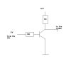
I know this must be really basic but I am trying to control a 12V circuit with a PIC (obvious 5v)
so I tried the following in the attached picture
the idea is
I apply ON/OFF (5V/0V) to the base with a RB=82K and a RC=300Ω
I need to generate a signal ON/OFF (12V/0V) in the arrow (for a H-bridge...)
but in the point with the arrow I only get 12V to 8V (and inverted!!!!)
What am I doing wrong????
I tried to put the resistor in the emitter and it goes from 0v to 2V
Help please
Kansai
Attachments
Last edited:
")
