Continue to Site

Welcome to our site!

Electro Tech is an online community (with over 170,000 members) who enjoy talking about and building electronic circuits, projects and gadgets. To participate you need to register. Registration is free. Click here to register now.

  • Welcome to our site! Electro Tech is an online community (with over 170,000 members) who enjoy talking about and building electronic circuits, projects and gadgets. To participate you need to register. Registration is free. Click here to register now.

Continuous Rotation Servo Speed Control

Status
Not open for further replies.

duda123

Member
Hello guys! I'm trying to build kind of a motorized small skate that moves front/back, with high precision movements (the speed should remain the exactly the same if not changed) and a speed controller.

Basically, it would need to be able to carry 4-5 kilograms on an horizontal surface, with a constant speed (that could be changed using a wired controller).

A friend recommended me to use a servo for the "high precision constant speed", but I don't know how to control a servo or how to make a speed controller for it. Also, I'm not sure if a servo can move a skate with 4-5 kilograms on top of it.

So, basically, I'd need to build a servo controller with on/off switch, invert direction switch and a speed "switch".

BTW, I'd really love if I could build that without any programming, since I don't have any hardware to write to chipsets.

I know I'm asking a lot of things, but it would be really awesome if you guys could help me with this project.

Thank you very much!
 
Last edited:
Basically, it would need to be able to carry 4-5 kilograms on an horizontal surface, with a constant speed (that could be changed using a wired controller).

What sort of frictional forces will you have? If it is on a level linear ball bearing, that weight can be handled with very little power.

A friend recommended me to use a servo for the "high precision constant speed", but I don't know how to control a servo or how to make a speed controller for it. Also, I'm not sure if a servo can move a skate with 4-5 kilograms on top of it.

You control it as you would any other servo. You need to produce a pulse of from 1 to 2 mS duration and repeated every 20 mS (i.e., 50 Hz). The simplest, non-microcontroller circuits use a NE555/LM555. Just search for servo controller. A microcontroller is really an easy way. Or, get a used RC transmitter and receiver. Depending on where you are, you will need the proper frequency for surface (i.e,. not for airplanes or helicopters)

Forward and reverse depends on the pulse width.

Finding a servo with sufficient power is probably not a problem. There are some very powerful servos available. Cost may be a factor, though.

This chart shows some of the servos available and which ones can be converted to continuous rotation:
**broken link removed**

This link is to a servo that is purpose-designed for continuous rotation. It describes some of the refinements you can make:
**broken link removed**

Finally, if you want a constant speed regardless of load, consider using a stepper motor instead of a servo. Stepper motors do require a different type of controller.

John
 
Hello John!

I don't need to keep a constant speed regardless of load, but when I set a speed, with the same load, I need it to keep a constant speed.
The load is going to be a video camera with a custom setup (different lenses, and all that kind of stuff).
Basically, I need to recreate the same camera movement more than once, that's why it's really important to keep the speed constant all the time. The "backward" movement is important to "reset" the camera.
BTW, I can buy an Arduino, if that makes things easier.

I'll add a picture showing what I'm trying to create!

CControl.jpg


Thank you very much for your reply!
 
A cheap (used) RC transmitter an receiver will give you wireless control. I don't think you can build that box for less. If you want to build your own and don't want to use a microcontroller, look up servo testers as I mentioned earlier. All you need is a joystick with potentiometer, or just use a knob on the potentiometer. Those testers all allow forward, backward, and speed control (when used with continuous rotation servos). If you want fixed speeds, then replace the potentiometer with fixed resistors and switches. The tester would be connected with wires as you have shown. If batteries are on the cart, then you only need a ground and signal wire from the cart to the controller, assuming the controller has its own battery.

The increased dead band for the Hitech servo is probably a good idea, if you want a good, solid stop and no creeping or buzzing when stopped.

John
 
John, the problem I've found with those servo testers is that I can't switch forward/backward with the same speed... Since I have to turn the potentiometer all the way back, I'll never be able to change it back to the exactly same position. My main problem is that I actually need a switch to invert the servo direction... I thought that maybe I could use an Arduino for that, but I'm not sure on how to properly connect the components and how to program the Arduino.

Ah, I don't really know what you mean by the RC transmitter and receiver... Do you mean a RC transmitter component and a RC receiver component?

EDITED: BTW, It's not necessary that the controller is wireless. It won't make any difference in my case :)

Thank you!
 
Last edited:
Why do you think that a switch to invert the servo direction will work any differently than sending the correct pulse width for the inverted direction? Are you sure the signal from the servo tester you used was correct? How do you know that?

Please give details about how you converted a servo to continuous rotation and the design of the servo tester that you used that didn't work as you wanted. Yesterday, you gave the impression that you hadn't done any testing.
A friend recommended me to use a servo for the "high precision constant speed", but I don't know how to control a servo or how to make a speed controller for it. Also, I'm not sure if a servo can move a skate with 4-5 kilograms on top of it.

There are several different designs for servo drivers/testers available. Some are more stable than others. The microcontroller-based ones as a whole are more stable than the single-chip, 555-based units. But, a two-chip design can be very stable.

Yes, you can use an Arduino, but I thought you didn't want to use a microcontroller . :confused:
BTW, I'd really love if I could build that without any programming, since I don't have any hardware to write to chipsets.

As for getting equal and reproducible speeds in each directions, that is where resistors and a switch come in.

John
 
John, I haven't done any testing! I haven't purchased the parts yet.

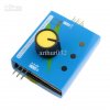
christmas-gift-new-3ch-esc-servo-tester-ccpm.jpg

To "invert" the direction of the servo, using this kind of tester, you must rotate the knob all the way to the other side. The problem is that, by doing that, you can't keep the same speed on both directions (FWD/BKWD).

About the Arduino, I could use one, since I can write to it using an USB port.

And just to be clear, I don't have a lot of knowledge in electronics and I don't even know how to send a pulse :)
 
Sorry, your comments are quite confusing.
John, the problem I've found with those servo testers is that I can't switch forward/backward with the same speed... Since I have to turn the potentiometer all the way back.

So to move on, a servo works on pulse width. Here is a link you need to read: **broken link removed**

There are of course other descriptions available.

The knob in the device you show in all likelihood is simply changing the ratio of two resistances. There is no assurance that the pulse width created by that device is even close to the same difference from center when the knob is moved an equal amounts in each direction. You can used fixed resistors and a switch to do that. On the other hand, that controller might be high quality and have excellent symmetry about center. We don't know until it is tested or you can examine the design. You can use a pulse width inverter to give approximately the same speed in reverse as you had in forward. It is an off-the-shelf device for models when you need to reverse servo direction. It uses a single chip and is easy to add.

Finally, I forgot to add that second-order effects may make a servo run at a slightly different speed forward than reverse given the same deviation from center pulse width. Wear on the brushes and/or gear train can cause that. The effect should be pretty small and can be compensated for in the design.

John
 
That is what I suggested above, but it is a little more complicated and not analog. That is, you will need to use a microcontroller. I thought you didn't need that degree of accuracy?

I think you need to make some decisions about in what direction you want to go.

John
 
Hm... I can use any kind of microcontroller that won't need an external writer to program. Is it much more complicated or just a little bit more?

About the accuracy, I'm not sure if the servo is going to be accurate enough for my project, since I need it to move at the same speed more than once.

I found this code for the arduino to control a stepper motor, with the ability to invert the direction and to set a custom speed, but I don't know how to set it up, since they don't have schematics.
**broken link removed**
 
About the accuracy, I'm not sure if the servo is going to be accurate enough for my project, since I need it to move at the same speed more than once.

Please tell us what you need. You have said you don't need stepper accuracy. Now, you seem be saying you do. In terms of cm/s what velocity do you need and to what degree of reproducibility (precision)?

John
 
I don't know how accurate a servo is...

I'll try to explain my project here.


There's an equipment sold for video cameras called a 'motion control'. This equipment is able to recreate the exactly same movement with a video camera more than once. Some people then created a "motorized slider" for cameras, that works basically the same way, but restrict the movements to an horizontal movement. I'm trying to accomplish something like a motorized slider, but in a cheaper and easier way.

My idea is basically to create a simplified motorized skate that can hold a constant speed that I set in a control. After recording the first footage, I'm gonna flip the switch to invert the motor's direction and wait until it gets close to the place it started. Then I'm gonna flip the switch one more time and it will recreate the exactly same movement from before.

I need the entire system to be accurate as possible, since small variations are going to be noticiable on the video. I don't work with motors and never did, so I don't know how accurate is a servo motor. I thought that it would be accurate enough, but from what you said, I thought that maybe it wouldn't be. So I'm really not sure whether I should use a servo motor or a stepper motor.

I'm sorry for not being able to answer you accurate enough, but I'm really in doubt about what should I do.


John, I'm probably going with the servo option:
https://openmoco.org/article/choosing-motor-type-your-motion-control-rig
 
Last edited:
I have no recent experience with video cameras and none in doing what you suggest. Certainly, one question will be whether it is a digital camera or video camera. From what you describe, you may want the skate to ride on linear ball bearings and use a timing belt driven by a stepper motor similar to what is done with CNC machining.

BTW, that reference's characterization of servo motors vs. steppers depends on true servo action, that is, feedback on position. A continuous rotation servo does not do that without additional components, such as an encoder. Your original truck with tires will not give you, "exact" positioning.

Hopefully, someone with experience in that area will chime in.

John
 
**broken link removed**

"Exact" is not very meaningful. I generally try to work to ±0.025mm for machine work, but end up +/- 0.05 mm . Anything more is quite a bit harder.

John
 
Last edited:
Another option, depending on engineering facilities available to you, might be to use a carriage driven along a lead screw shaft rotated by a geared DC model motor. A simple optical encoder could be used to sense shaft rotation angle/rate and provide a feedback signal to control motor speed.
 
That's a belt-driven carriage; not a lead screw type.
 
Timing belt drives are used on some commercial CNC routers (e.g., Romaxx) and DIY CNC (https://www.inventables.com/technologies/desktop-cnc-mill-kits-shapeoko). They can be quite precise, if not overly stressed, and are considerably cheaper than a ground ballscrew. They are not too good for heavy milling, but even on Bridgeport conversions, the linkage between the stepper and ballscrew (leadscrew) is often a timing belt, because there is a ratio reduction and the belt is not stressed. From the little information provided so far, a belt may suffice. I would be more concerned about slop and jiggle from the track and rollers shown in the YouTube example.

Duda123 needs to put some numbers to her/his design. Otherwise, we will just be shooting in the dark. This project started out being just a servo running a small trolley with tires and depended on the electronic center (i.e., the dead band). It has now seemingly evolved into needing micrometer precision.


If one goes to Servo City (https://www.servocity.com/), you can find the dead band. For most analog servos (i.e., the ones likely to be converted to continuous rotation), you will see that the dead band is about 5 to 8 uS. The full range is +/- 500 uS for +/-60° or so. Using a dimensioned sketch and known gear ratios, one could calculate its positioning accuracy. 2uS is about as small a dead band as one can find in hobby servos.

BTW, I am not recommending or criticizing Servo City as a vendor. It is simply a single location with a lot of technical information for a large number of servos.

John
 
Last edited:
Status
Not open for further replies.

Latest threads

Back
Top