Hey guys I'm new to the forums. I'm trying to build a circuit for a "Traffic Light". I want the three lights (Red, Yellow, Green) to continuously run one arter another. The outputs which are the lights are going to be Light Bulbs.
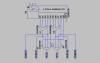
So far I have look at my notes, (I took electronics throughout High School) and I have the 555 timer and the 74194 TTL IC. Me and my friend figure out that the shift right recirculating circuit will be good for this. Being the 555 timer the clock of the 74194 TTL.
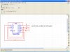
So my questions are, am I on the right track? Where can I find the circuit diagram for this because I'm trying to design this on Multisim.
If not, is there a better and easier circuit for this?
Thanks.
So far I have look at my notes, (I took electronics throughout High School) and I have the 555 timer and the 74194 TTL IC. Me and my friend figure out that the shift right recirculating circuit will be good for this. Being the 555 timer the clock of the 74194 TTL.
So my questions are, am I on the right track? Where can I find the circuit diagram for this because I'm trying to design this on Multisim.
If not, is there a better and easier circuit for this?
Thanks.