Continue to Site

Welcome to our site!

Electro Tech is an online community (with over 170,000 members) who enjoy talking about and building electronic circuits, projects and gadgets. To participate you need to register. Registration is free. Click here to register now.

  • Welcome to our site! Electro Tech is an online community (with over 170,000 members) who enjoy talking about and building electronic circuits, projects and gadgets. To participate you need to register. Registration is free. Click here to register now.

constant current sources connected in series

Status
Not open for further replies.

swordfish12

New Member
hi everyone, I have a small doubt,
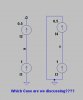
what is the current in a circuit that has only two constant current sources(one is I amp and the other one is I/2 amp) connected in series. the circuit does not have any other components.
 
Any open-circuited current source puts out an infinite voltage. Putting two open-circuited current sources in series changes nothing...
 
Hello there,


If both current sources are connected together but nothing else connected (assuming a continuous circuit) then the one with the higher current goes to an infinite voltage and the other goes to zero voltage.

However, if both current sources are exactly equal in value then we can look at the voltage across each one. For a circuit with two in series and also some small resistance of the connecting wires, both sources will produce the same voltage which will be half of the current times the resistance of the wire resistance.
It should be noted though that this is only possible in theory, because there is no way to get the same current in two sources that are exactly the same, and i mean exactly not off even by 1e-99 amps. Even a tiny difference upsets the balance so this could not work unless we also assume the ever present parallel resistance which could be high but still significant in determining the two voltages.

To understand this better, try placing two equal resistances that are very high in value one across each current source, and some tiny resistance in series with the two sources in series.

In short, it's not something we would want to do except as a theoretical exercise.
 
If one open-circuited current source puts out infinite volts, wouldn't two connected in series put out 2χ∞ Volts? ;)
 
Hi Mike,


Well isnt the one with the lower current going to be satisfied with it's current? I was talking about when they are connected together to form a complete circuit as mentioned. If they are both open circuited then there's no way for current to flow.
 
What is 2χ∞?
 
Are these real current sources or theoretical ones?
 
Hi,

They have to be theoretical for anything to work, so in effect we're talking about very very special circumstances.

To see this work we would have to set both current sources to the same value, with some tiny series resistance, and have them all connected in series. We'd also have to connect some large resistances across the two current sources both the same value. So 10M across each source, 0.001 ohm in series with both current sources in series. We could then let the 10M resistors go higher and higher.

Might not even be worth discussing cause it is not practical in any form. Maybe some very rare case out there.
 
They have to be theoretical for anything to work, so in effect we're talking about very very special circumstances.
In the case you need an infinity-doubler perhaps.

If theoretical, it is meaningless to have just two different current sources in series.

If real, then the answer is 0.5I Amps.
 
Last edited:
Ideal current sources in series is the same as ideal voltage sources in parallel.

If they are not identical, it will not work, the result is nonsense.

JimB
 
I/2. The "I" current source will essentially be unregulated or at it's max V rail for all practical importance. Think of the current sources as I-Limiters. Which one wins?

The "I" source will end up being a voltage source at the max compliance voltage.
 
Which case are we discussing?
 

Attachments

  • DF40.jpg
    DF40.jpg
    45.1 KB · Views: 393
The rightmost case, where the non-ideal sources are in a circuit. Otherwise there is no current flowing.
 
Hi,

As i said two times previously, there is no reasoning for two current sources in series unless we assume some non ideality such as a large resistance in parallel with each source and a small series resistance in series with both. So the circuit i am referring to is:
Two current sources in series, with also a small resistance like 0.001 ohms in series with both.
The two current sources have a large resistance like 10 megohms in parallel with each one.
So that is a total of three resistors, two current sources.

Once we have this circuit established, we can then let the 10 meg's go higher and the 0.001 go lower and see what the effect is.

If both current sources have the same value (say 1 amp to make this simple) then we see some reasonable results. But they must be exactly the same. If they are even a tiny bit different then that affects the outcome.

If this still isnt clear i'll do the whole circuit so we can see what happens. It's mildly interesting mostly because it was already brought up, but in real life i dont think it has any application unless we limit the top end current of the sources, like say to 10 amps or something, so they cant go any higher. Then we might have created a logic gate :)
 
Sorry to bring this down to Earth, but why would anyone connect two constant current sources in series?

Don't see the point... which is clearly (and correctly) what Mr Al is saying in the previous post
 
Hello,


Yes i am saying that there is probably very limited application for this kind of thing, but that never stopped us from looking at the theory behind it as usual. There are other cases out there where there is almost no application but the theory is still looked at. For example, i've never seen a real life resonant circuit that has perfect critical damping, yet the theory has been out there for decades.

All i was saying was to investigate this sanely we could set up a circuit that is 'almost' a perfect set of sources in series, then go from there.

The dual to the two current sources in series is the two voltage sources in parallel. We can quickly see here that there is wide application for this in real life even though we cant theoretically connect two voltage sources that are not EXACTLY the same in parallel because an infinite current would flow. But in real life there is always some small but significant series resistance that stops this from happening. Battery packs are wired in series and parallel.
The dual to the two voltage sources with resistance in series is the two current sources with resistance in parallel to each one. That makes it at least possible to analyze without allowing infinite currents or voltages to appear. And if we do anything to the circuit after that that causes the voltage of one or both current sources to rise, then we see what happens as we get closer and closer to ideal current sources.

So again this is a theoretical thought exercise for the most part, but may be a little interesting anyway just to satisfy the curiosity :)

Sometimes theory is used as a leveraging tool also as in, "Well it's not that special theoretical case here, so it must be something else then".
 
Hi again,


I think an interesting key point that comes out of all this is that in theory it does not depend on what a current source is connected to because it always pushes out the current it is assigned. For example, if we connect the 'arrow head' end of a current source of 1 amp to a resistor of 1 ohm (other end of resistor to ground) we see a voltage across the resistor of 1 volt, and it doesnt matter what the other end of the current source is connected to...it can be a ground which is zero volts, or a voltage source of 1 volt, 2 volts, 100 volts, 1000 volts, a million volts, we still see 1 volt across that resistor.

Another key point is that it doesnt matter what impedance we connect that other end (the tail end) of the current source to either, it still puts 1 amp through that 1 ohm resistor and that produces 1 volt across the resistor. This can be reasoned out by noting that the current source already has an infinite internal resistance, so it isolates the current through the resistor from everything else forcing it to be a set value like that 1 amp.

In a real life circuit of course there is a big difference. For one thing, we cant even develop an infinite voltage nor can we produce a perfect current source.
 
Assuming I = 1A, the answer is indeterminate but lies between 1A and 0.5A and can be shown in two ways that give identical answers.
I think the more general case also applies and the current is between I and I/2 and is indeterminate.

A current source can be modeled as a V in series with an R, with V/R = I and both V and R very high. As you have the V and R of each of the two sources step through 1v, 10v, . . . 100,000,000v and 1 or 2 ohms, 10 or 20 ohms, on up, you will have 81 combinations of V1 and V2 and so if you make a histogram of I you will find a preferred value between I and I/2, but the exact value is still indeterminate. This can be shown on a spreadsheet.

Thanks for a fun problem!
 
Last edited:
Status
Not open for further replies.

Latest threads

Back
Top