Continue to Site

Welcome to our site!

Electro Tech is an online community (with over 170,000 members) who enjoy talking about and building electronic circuits, projects and gadgets. To participate you need to register. Registration is free. Click here to register now.

  • Welcome to our site! Electro Tech is an online community (with over 170,000 members) who enjoy talking about and building electronic circuits, projects and gadgets. To participate you need to register. Registration is free. Click here to register now.

constant current source

Status
Not open for further replies.

unlv007

New Member
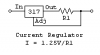
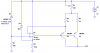
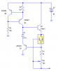
I want to understand how the circuit 1 and 2 drawn below act as constant current source. Please explain the concept
My requirement of current source is such that-
(1) compliance voltage=50V.
(2) the load the current source drives=1K-2K range. Hence i want the output resistance much higher than this value.
how do i choose the transistor /other components to ensure (1) and should i connect a buffer circuit to obtain the output imepance or are these circuits sufficient?
 

Attachments

  • circuit1.gif
    circuit1.gif
    1.6 KB · Views: 534
  • circuit2.PNG
    circuit2.PNG
    1.5 KB · Views: 400
If you read the LM317 datasheet, it says that the way it works (as a voltage regulator or current regulator) is that it modifies it's output to maintain try and maintain a 1.25V between the output and adjustment pin. If you wire it as a current source, what it tries to do is push enough current through that resistor to always keep 1.25V across it. Constant voltage across a resistor means constant currrent, and since "zero" current flows into the adjustment pin, all the current in the resistor goes to the output making your current source.

It does this same thing when working as a voltage source, the only difference is that you have two resistors instead of one (look at the regular voltage regulator circuit in the LM317 datasheet). The LM317 drives the current through the resistor between Vout-ADJ to keep the voltage across that resistor at 1.25V, but since the current must flow through both resistors (no current flows into the ADJ pin), the result is that the voltage across both resistors is higher than 1.25V- your regulated voltage which is determined by the values of resistors used.

The other circuit works the same way.

If you understand how this works, then the operation of all linear current sources is very similar (hint: the way all op-amp circuits work is they modify their output so that the voltage and + and - input terminals are equal, including this case):
https://en.wikipedia.org/wiki/Image:Op-amp_current_source_with_pass_transistor.png

Remember that a current source has to be able to output a voltage that is AT LEAST as high as
V = Iconstant/Rload

So if you want 500mA going through a 2K resistor, this means that the current source has to output 2000V, and thus needs a power supply even higher than 2000V and components to withstand this voltage. Obviously, this is a very hard current source to find.

THe reason those current sources can only drive loads 1K-2K range is because their output voltage isn't high to be able to drive their maximum possible current through resistors any larger than that. So if you want a stronger current source (one that can drive more current through a higher resistance), then you need to have a higher voltage supply and components that can tolerate that- and that's the only difference, higher source voltages and components that can withstand that source voltage. That's how you select the components.

No buffer should be needed because the current sources ARE amplifiers/buffers wired with feedback to produce that output. If you used a buffer it would be like wiring two current sources in series- pointless. It work with voltage because voltage doesn't "flow", so buffers cascade to increase the voltage or buffer it or whatever. But current does flow, so if you cascade it, then the later stages just block the current from the first stage stopping it from appearing on the output. You'd have to use parallel current sources so all the current combines at the output, but then you have balancing issues between all the current sources in parallel since they are never identical and might start to fight each other. It'd be best to only use one stage and but use a amplifier that can handle more current for that stage.
 
Last edited:
My load current is only up to 50mA and so i want to design for source for 50Volts.
that gives R= 1.25/0.05=25 ohms.
So if i just connect a 25ohm resistor, i believe i will get a current source that generates 50mA provides 50V through a 1K resistor.
To get current from 10mA to 50mA i need to connect a potentiometer 25 to 125 ohms. Will that be adequate? or do i need to bother about any more considerations?
 
50V can only drive 50mA through resistors that are 1kohm or smaller (or is that what you meant by significantly larger load?)

Because we normally say a small resistance is a large load, but that's only because we normally talk about voltage sources. (Takes more current to achieve the desired voltage with a small resistor).

With a current source, a large load is a large resistor since it takes more voltage to achieve the required current in a large resistor.

All you need is a 50V source (or a bit higher than that since linear devices do have a dropout) and an op-amp that can withstand your desired current and voltage levels to toss into a feedback circuit on the wikipedia page I sent you. TI has some high voltage op-amps such as that OPA547, 548, and 549. DO NOT forget to calculate the power dissipation in the op-amps. It's working by burning off extra voltage from the 50V supply, so it gets hotter as it provides less current in your current source and could be a lot of heat.

Or you could take your transistor circuit and use a transistor capable of tolerating 50V + some overhead voltage. Again, do not forget about the power dissipation as it works by burning off extra voltage as heat.

The worst case power dissipation is 50mA through 125 ohms which is 312.5mW- higher than the 250mW limit for most potentiometers. REmember, that the 25-125R resistance range is if you use a 1.25V reference like the LM317 in your circuit. You cannot actually use the LM317 because it cannot handle 50V. You can easily use other voltage references (and thus different resistor values that may dissipate less heat) now that you seem to understand how everything works from your calculation of the required resistance. I'm glad it seems you either understood my explanation or where able to figure out how it works from the Wiki link (something I wasn't expecting).

Those are what you need to take into account- power dissipation power! dissipation!
 
Last edited:
dknguyen said:
The worst case power dissipation is 50mA through 125 ohms which is 312.5mW- higher than the 250mW limit for most potentiometers.
But 50mA * 125 ohms is 6.25V. The pot wll not have to dissipate 312.5mW, but it will have to handle 50mA max. I wouldn't think this would be a problem.:confused:
 
Roff said:
But 50mA * 125 ohms is 6.25V. The pot wll not have to dissipate 312.5mW, but it will have to handle 50mA max. I wouldn't think this would be a problem.:confused:

What are you talking about? All the 50mA flows through the 125 ohm resistor. So the I^2*R loss in the resistor is 312mW. And if course, the V^2/R loss is also the same.
 
Last edited:
dknguyen said:
What are you talking about? All the 50mA flows through the 125 ohm resistor. So the I^2*R loss in the resistor is 312mW. And if course, the V^2/R loss is also the same.
It's a resistor with 50mA flowing through it and 1.25V across it. How much power is that?
 
Oh, yeah that's right- the maximum current doesn't run through the maximum resistance. As one rises the other falls.
 
50V is too high for an LM317, unless you add a series resistor to drop the voltage enough.
 
Here are a couple of 10mA - 50mA, 50V compliance current sources that work OK in simulation.
EDIT: The transistors in the first circuit will not handle the power disipation of a load where the current is high but the output voltage is low.
 

Attachments

  • 50V compliance current source.PNG
    50V compliance current source.PNG
    13.7 KB · Views: 379
  • bootstrapped LM317 current source.PNG
    bootstrapped LM317 current source.PNG
    9 KB · Views: 367
Last edited:
hi,
A basic CC source for 50mA into a S/C as per diagram.

My requirement of current source is such that-
(1) compliance voltage=50V.
(2) the load the current source drives=1K-2K range. Hence i want the output resistance much higher than this value.

If the Vcomp <=50V how can your load resistance be 2000R, when you require 50mA CC.?

What voltage source do you have available.?
 
Last edited:
Thanks everybody for your wonderful circuits. The answers to your questions

1) The voltage source i have is a power supply with two modules, each producing 30-31V. i can join the two modules in series to get 60V.
2)My load is 1K not 2K.
so please suggest/modify the const current circuits to pass 1mA TO 50mA
regards
 
On1aag pointed out the TL783 to me in a PM. It's functionally a high-voltage version of the LM317. It should work in this application, but I have not tested it, and TI does not provide a spice model.
 
thank you very much,
I would like to implement the circuit suggested by roff and eric gibbs, however i must have my lab running tomorrow, so in case i do not have the devices listed to buy from kiesub electronics here at las vegas, i must have an alternative so that the circuit can be built tomorrow positively.
In Roff's circuit
1) in his first circuit, please suggest alternatives to TL071 ,LM 385-2.5.
i THINK 2n5401 is commonly available i guess.
2) In ROFF'S BOOTSTRAP LM317 circuit, please suggest alternatives to TIP 41C.
iN ericgibbs CIRCUIT, please suggest equivalen alternative to TIP 42 in case this is not available.

Just to recap, i need const currt ssource 1mA to 50ma, LOAD=1K,compliance voltage=50V
Thank you for your precious help.
 
Status
Not open for further replies.

New Articles From Microcontroller Tips

Back
Top