Continue to Site

Welcome to our site!

Electro Tech is an online community (with over 170,000 members) who enjoy talking about and building electronic circuits, projects and gadgets. To participate you need to register. Registration is free. Click here to register now.

  • Welcome to our site! Electro Tech is an online community (with over 170,000 members) who enjoy talking about and building electronic circuits, projects and gadgets. To participate you need to register. Registration is free. Click here to register now.

Connecting logic gate to DFF's input

Status
Not open for further replies.

EngIntoHW

Member
I'm not sure whether the following scheme is valid:
untitled-jpg.45963


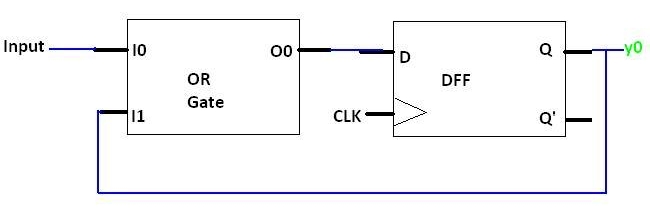
As now, instead of having the input to be steady for Tsetup before the clock's rising, it needs to be steady for Tsetup + T(OR_GATE).
(Where T(OR_GATE) is the time it takes to the OR gate to output a valid value).

What do you think please?

Thank you.
 

Attachments

  • Untitled.jpg
    Untitled.jpg
    29.8 KB · Views: 440
For that circuit, once the DFF Q output goes high after the CLK pulse due to a logic one on the input, it will stay high independent of the further state of the input. Is that what you want?
 
If the clock and the input are asynchronous it really doesn't matter. Sometimes you will get it sometimes you won't.
 
Yes,

My main goal was to design a circuit which outputs 1 for a single clock, when the first '1' is received in input, and then it always outputs '0's.

So I was intending to connect the output of this circuit to the input of a differentiator.
 
As I said, your circuit will output a "1" and then stay at "1" until reset or the power is removed. But if it inputs to a differentiator that may be ok.

To do as you want, you could change the OR gate to an AND gate and add a latch between the FF output and the input to the AND gate.
 
As I said, your circuit will output a "1" and then stay at "1" until reset or the power is removed. But if it inputs to a differentiator that may be ok.
Thanks for the confirmation.

To do as you want, you could change the OR gate to an AND gate and add a latch between the FF output and the input to the AND gate.
Perhaps you could draw it?

And what would be the EN input of the D-Latch?
 
Below is a simulation using a 4013 dual-D FF to generate only one output pulse with the input goes high (the Space switch). I used the second FF as a latch.

Note that all unused inputs must be connected to ground, which I did not show. Also you will need a signal to initialize both FF's in the desired state when powered up (CD1 and CD2 momentarily high, then low, which could be done with an RC circuit).

One-Shot FF.jpg
 
Last edited:
Hey Crutschow.

I was trying to draw your schematic:

aaa-png.45992


Did I draw it correctly?
And, What connects to EN of the D-latch?

Thanks :)
 

Attachments

  • aaa.png
    aaa.png
    8.7 KB · Views: 306
Your schematic is not correct. Q1 goes to the "SET" input of the second FF.

I don't know what "EN" is. There is normally the "D" input, the "CLK" input, and the "SET" and "RESET" inputs.

Just follow the schematic I posted.
 
I thought that a D-latch is a Latch with EN and D entries.

I got it now.

However, for input:
0010-0010
You'll receive:
0010-0010

Isn't it?
 
However, for input:
0010-0010
You'll receive:
0010-0010

Isn't it?
Don't know what that means. As my simulation shows you get one pulse out when the input goes high. After that it makes no difference what the input does.
 
Don't know what that means. As my simulation shows you get one pulse out when the input goes high. After that it makes no difference what the input does.

You are right! it's brilliant :)

This D-Latch doesn't operate with a clock, right?

Is there any advantage of using your system and not the one I suggested? (which was: OR Gate -> DFF -> Differentiator).
 
Last edited:
This D-Latch doesn't operate with a clock, right?

Is there any advantage of using your system and not the one I suggested? (which was: OR Gate -> DFF -> Differentiator).
A latch, by definition, does not normally use a clock. It usually has just a set and reset input.

Which circuit is better depends upon what you are trying to do with the signal. I can't answer that.
 
does anyone know if the prgram rx logix can run with a mac OS
If you want an answer, start a new thread, don't try to hijack this one.
 
Status
Not open for further replies.

Latest threads

New Articles From Microcontroller Tips

Back
Top