Continue to Site

Welcome to our site!

Electro Tech is an online community (with over 170,000 members) who enjoy talking about and building electronic circuits, projects and gadgets. To participate you need to register. Registration is free. Click here to register now.

  • Welcome to our site! Electro Tech is an online community (with over 170,000 members) who enjoy talking about and building electronic circuits, projects and gadgets. To participate you need to register. Registration is free. Click here to register now.

Configuring output of DAC5672 to be differential

Status
Not open for further replies.

pavjayt

Member
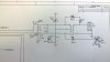
I am using a TI DAC5672 to design a DAC board to have a bipolar analog output. On the eval board they have layout for both single ended or differential outputs. The differential output is transformer coupled. I am wondering if I should go with their design of using a 1:1 Impedance ratio transformer schematic (page 15, table 2-3) or should I use an op-amp based design like I was using with AD7533.

Any ideas/suggestions?

thanks
 

Attachments

  • WP_20151012_11_26_23_Pro.jpg
    WP_20151012_11_26_23_Pro.jpg
    1.5 MB · Views: 166
If you are concerned about noise on your analog signal, then differential will be the way to go. Especially if the stage following the DAC has a lot of gain.With differential, noise picked up on the input cancels out where single ended will just amplify noise coupled into the input net.
 
If you are concerned about noise on your analog signal, then differential will be the way to go. Especially if the stage following the DAC has a lot of gain.With differential, noise picked up on the input cancels out where single ended will just amplify noise coupled into the input net.
Thanks Mike for your response. I would like to go with differential output for sure. Just debating whether to use the schematic I used for AD7533 (page 8, bipolar operation) something on those lines or go with transformer coupling as shown in eval schematic. The next stage for this outputs is as inputs for AD8004 (gain is at max 2) that we are discussing in the other thread that you just replied to.
 
I just tried to use DAC5672EVM board which is factory set to 1:1 transformer coupled output and it turns out there is nothing coming out of the board when I have the input data on both ports as well as the clock is connected to it. Tried to contact TI on this and they said to use E2E forums to post my question which I did and waiting for their response for couple of days now. This board works fine when we modify it to SE output without any problems, but not in factory set configuration.

Any ideas why it isn't working?
 
Status
Not open for further replies.

Latest threads

New Articles From Microcontroller Tips

Back
Top