Electro Tech is an online community (with over 170,000 members) who enjoy talking about and building electronic circuits, projects and gadgets. To participate you need to register. Registration is free. Click here to register now.
Welcome to our site! Electro Tech is an online community (with over 170,000 members) who enjoy talking about and building electronic circuits, projects and gadgets. To participate you need to register. Registration is free. Click here to register now.
I find it highly amusing to see syncronous counters in an asyncronous design.
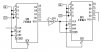
To convert the divide by six into a divide by ten just change the preload on the first counter from the value "10" to the value "6". The count sequence will be:
Code:
6 7 8 9 10 11 12 13 14 15 6 7 ...
The way the second counter is set up it can only provide a divide by a power of 2.
HI and LO appear to represent logic 1 and logic 0 as you surmised.
Well you already have the first one by changing the preload value from "1010" = 10, to "0110" = 6. Inverted RCO is the clock for the next stage which is constructed the same as the first stage with the same preload of "0110" but now the inverted RCO has to go back to load on the second stage. This will give you an asyncronous divide by 100
This site uses cookies to help personalise content, tailor your experience and to keep you logged in if you register.
By continuing to use this site, you are consenting to our use of cookies.