Continue to Site

Welcome to our site!

Electro Tech is an online community (with over 170,000 members) who enjoy talking about and building electronic circuits, projects and gadgets. To participate you need to register. Registration is free. Click here to register now.

  • Welcome to our site! Electro Tech is an online community (with over 170,000 members) who enjoy talking about and building electronic circuits, projects and gadgets. To participate you need to register. Registration is free. Click here to register now.

Component identification

Status
Not open for further replies.

ljcox

Well-Known Member
I am tracing the circuit of a computer power supply unit (PSU), it blew up and I'm trying to discover why.

It has 2 identical components that I can't identify.

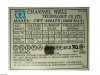
The attached photo, shows the PSU label with one of the components laying on it.

As you can see, it has SUM1-PA printed on it. They are designated V1 & V2 on the PCB.

Their position in the circuit makes me assume that they are voltage spike suppressors.

I did an internet search for a data sheet but no result.

Does anyone know what it is?

Any advice will be appreciated.
 

Attachments

  • Component.JPG
    Component.JPG
    102 KB · Views: 239
Looks like a capacitor or surge-supressor with a heatshrink tube covering it. Can you remove the heat shrink with a razor blade?
 
Yes, Len, They are MOVs gripped in a heatshrinkable sleeving, as rightly pointed out by ParkingLotLust. This sleeve helps protect damages from blasted MOV in adverse conditions.
 
Thanks for the replies.
I took the HST off and it is a TUR 07271.

There are also 3 blue devices that look like capacitors that I believe to be MOVs as they are very similar to MOVs that I've used in the past. They have 472M printed on them.

The TUR devices are labelled V1 & V2 whereas, the blue ones are CY1, CY2 & CY3.

Also, the TURs are smaller than the blue.
 
Nigel Goodwin said:
They sound like 4700pF capacitors?.
Thanks Nigel.

That's what I thought, but I measured the capacitance of each (using my Atlas LCR meter) and they are 3.8 nF, 8.7 nF & 8.6 nF approx.

Whereas, I measured four 4.7 nF caps and they were in the 4.3 ~ 4.9 nF range.

I could not measure an actual MOV as I don't have one handy.

Also, their positions in the circuit are consistent with MOVs.
 
Last edited:
MOVs -- perhaps not possible to check except it should show M:eek:hm: s under normal situation.
there are spike simulating machines for checking the Device but we only see the physical conditions and satisfy. If there are cracks on thew body(exactly parallel to the circumference), better replace.
 
Status
Not open for further replies.

Latest threads

New Articles From Microcontroller Tips

Back
Top