Continue to Site

Welcome to our site!

Electro Tech is an online community (with over 170,000 members) who enjoy talking about and building electronic circuits, projects and gadgets. To participate you need to register. Registration is free. Click here to register now.

  • Welcome to our site! Electro Tech is an online community (with over 170,000 members) who enjoy talking about and building electronic circuits, projects and gadgets. To participate you need to register. Registration is free. Click here to register now.

Component Identification

Status
Not open for further replies.

jimbo6871

New Member
Hi Guys,

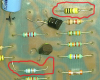
I'm working on an old amplifier from late 70's early 80's and need a bit of help with a couple of components, I think both are caps but I'm not great with electronics (thought this might be a good way to learn a bit :D )

Anyway both components ringed in red in the attached picture.

Thanks in advance for the help.

Jim
 

Attachments

  • upload_2014-7-5_10-50-52.png
    upload_2014-7-5_10-50-52.png
    566.6 KB · Views: 200
  • Caps.png
    Caps.png
    566.6 KB · Views: 206
They are resistors. 100K, at the bottom and 10 Ohm at the top (in doubt of this last, honestly).

The light blue thing partially shown on the left (top) is a cap.
 
The "Brown Black Yellow" at the the bottom of the picture looks like a 100k Ohm resistor to me.

The "Brown Black Black Gold(?) White(?)" could be 10 Ohm or 1 Ohm depending on the coding, difficult to say.

JimB
 
Thanks guys,
Tin can caps and some ceramics I'm familiar with but these two have been driving me mad (and being a complete novice is'nt helping either, lol).

I turned up a schematic and it confused me more as all the caps I recognised were given a 'C' prefix and then these two have 'C' (c25 & C22) prefixes as well so I completely hit a wall with these two :banghead:

here's a bigger pic of the board and a scan of the schematic
 

Attachments

  • tnt100.jpg
    tnt100.jpg
    1.6 MB · Views: 186
  • PV TNT100 '79-1.pdf
    778.1 KB · Views: 153
Hi,
Those are axial ceramic capacitors. Their color code is given here: **broken link removed**
Its very easy to confuse them with resistors, as your other respondents have done. Judging from the images you have uploaded, it would appear that the resistors have a slight waist to them, which isn't the case with the axial ceramics.
Also, here is the Google image page for axial ceramics: https://www.google.co.uk/search?q=a...6M7Ab1nIGgAw&ved=0CAgQ_AUoAQ&biw=1455&bih=705
 
Thanks for that ramuna,

I have to admit though I'm still a bit stumped with these, the yellow body one is Brown, Black, Black, Gold and White and the schematic says it's 100PF (Brown, Black, Black, - makes sense) but what about temp, voltage, tolerance, coupling / bypass. Sorry if I'm asking really numpty stupid questions, I'm just not sure if it's because I'm looking at a 30+ year old cap or if it's my total lack of knowledge and ineptitude. :confused:
 
Hi,
See the marked capacitors in the attached image. It appears that for C25, a 10pF capacitor (Brown Black Black....) has been inserted instead of the 100pF one shown in the schematic. It's difficult to clearly see the colours for temperature coefficient & tolerance in your uploaded images, so I'll give you my best guess;) (but to be honest, with such ancient capacitors, these two values are insignificant relative to the capacitance values). The colour codes for the marked capacitors are: (1) C22 = Brown Black Yellow Grey? = 10x10,000 = 100,000 pF = 0.1 uF, temp. coeff of +30 (2) C23 = Brown Black Brown Gold White = 10x10 = 100 pF. Here I will interpret the Gold as being 5% Tolerance, as in resistors and White as being the temp coefficient (non-standard colour for capacitor tolerance, but this interpretation is the most probable) (3) C25 = Brown Black Black Gold White = 10x1 = 10 pF, same interpretations for Gold & White as in item (2).

Incidentally, the resistor on the top right of your image tnt100, is burnt out.
 

Attachments

  • AmpCircuit.jpg
    AmpCircuit.jpg
    325.4 KB · Views: 162
Incidentally, the resistor on the top right of your image tnt100, is burnt out.

At least, it looks weird if compared with the rest. Isn't it a diode of sorts?
 
At least, it looks weird if compared with the rest. Isn't it a diode of sorts?

Yip well and truly a burnt out resistor, the board was pretty bad all round, so far I've replaced 22 components on it o_O but, hopefully the end is in sight:)

Two tin can caps and these two to replace and hopefully :nailbiting: it will live again!
 
so far I've replaced 22 components on it o_O but, hopefully the end is in sight:)

Can you presume the reason for the failure? That amount of components seem like too much...:woot:

Not knowing the cause and replacing blindly is not the best way, I think. Good luck anyway.
 
Seems to have been a combination of aged and dry caps, leaky caps, and a transistor that just had enough punishment and finally went up in smoke! :eek:

Although old, its not a very complex amplifier, so lifting each component and testing it out of circut only took a few hours. So.... the cause looks to be nothing more than old age!
 
Good detective work Jimbo!
I must admit that colour codes on axial caps are a mystery to me, but don't forget that you can lift one end of an unknown component and measure it with a multimeter on resistance range - a cap will, of course, read like an open circuit. It won't tell you anything about the cap's value of course, but it will at least give you a clue as to what you're looking at.
I've also seen zener diodes in very similar packages. As has been mentioned previously, you can generally see the end caps on a resistor giving it a thinner waist in the middle, a slightly different shape to caps and diodes.

Keep us informed on the progress.
 
Status
Not open for further replies.

Latest threads

New Articles From Microcontroller Tips

Back
Top