tomizett
Active Member
Hi All,
I've recently had cause to build a sweepable audio frequency sinewave oscillator. Since I was hoping for a low distortion, I thought that a design incorporating an automatic gain control (AGC) was the only option. I've not had much sucess and so I've opted just to build someone else's published design, but it did make me realise that stabalising this kind of oscillator seems to be more complicated than it first appears.
I'm trying to gain a better understanding of how I could design this type of circuit if I did need to, and I'm hoping that some of the good folks here might be able to give some insight.
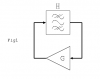
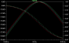
The basic idea (see fig 1) is that you have a filter or some kind of phase shift network that provides a 360 degree phase shift at the ocillation frequency, with some gain H. This is connected in a feedback loop with an amplifier of gain G. You arrange for the product of G and H to be 1, and the oscillations stay at a steady amplitude. So far so simple.
The tricky part is that you have to watch the output of the oscillator and continually adjust the gain of the amplifier (G) to keep the amplitude both stable and at the desired level.
We'll leave asside the practical matter of low-distortion variable gain amplifiers for the moment, but we do have to take into account ripple voltage on the control signal as any component of the control voltage at (multiples of) the signal frequency will manifest as distortion.
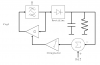
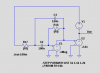
The standard solution seems to be as figure 2. The output is simply rectified, filtered and used to reduce the gain G in proportion to the output level. I think this model covers all stabalisation techniques using thermistors. lamps etc (give or take some nonlinearity).
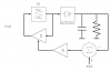
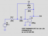
An obvious step on from this, to give tighter amplitude regulation, is fig 3, where an integrator is used. I've just drawn this in case anyone want's to "point to" it.
The main confounding factor here seems to be that the rate-of-change of the output amplitude depends not only on the gain G, but also on the oscillation frequency. Because of this, it seems to me that you would need some kind of proportional-derivative control loop, where the derivative part took care of making the product H x G exactly 1 (so that each cycle was exactly the same as the last) and then the proportional part could adjust this to swing the output level towards a set point. It doesn't sound very likely in practice though.
The bottom line here is that I'd be interested to hear how those of you with a better understanding of control systems than me (and that's most of you!) would go about designing this kind of oscillator for minimum distortion and minimum settling time.
I've recently had cause to build a sweepable audio frequency sinewave oscillator. Since I was hoping for a low distortion, I thought that a design incorporating an automatic gain control (AGC) was the only option. I've not had much sucess and so I've opted just to build someone else's published design, but it did make me realise that stabalising this kind of oscillator seems to be more complicated than it first appears.
I'm trying to gain a better understanding of how I could design this type of circuit if I did need to, and I'm hoping that some of the good folks here might be able to give some insight.
The basic idea (see fig 1) is that you have a filter or some kind of phase shift network that provides a 360 degree phase shift at the ocillation frequency, with some gain H. This is connected in a feedback loop with an amplifier of gain G. You arrange for the product of G and H to be 1, and the oscillations stay at a steady amplitude. So far so simple.
The tricky part is that you have to watch the output of the oscillator and continually adjust the gain of the amplifier (G) to keep the amplitude both stable and at the desired level.
We'll leave asside the practical matter of low-distortion variable gain amplifiers for the moment, but we do have to take into account ripple voltage on the control signal as any component of the control voltage at (multiples of) the signal frequency will manifest as distortion.
The standard solution seems to be as figure 2. The output is simply rectified, filtered and used to reduce the gain G in proportion to the output level. I think this model covers all stabalisation techniques using thermistors. lamps etc (give or take some nonlinearity).
An obvious step on from this, to give tighter amplitude regulation, is fig 3, where an integrator is used. I've just drawn this in case anyone want's to "point to" it.
The main confounding factor here seems to be that the rate-of-change of the output amplitude depends not only on the gain G, but also on the oscillation frequency. Because of this, it seems to me that you would need some kind of proportional-derivative control loop, where the derivative part took care of making the product H x G exactly 1 (so that each cycle was exactly the same as the last) and then the proportional part could adjust this to swing the output level towards a set point. It doesn't sound very likely in practice though.
The bottom line here is that I'd be interested to hear how those of you with a better understanding of control systems than me (and that's most of you!) would go about designing this kind of oscillator for minimum distortion and minimum settling time.