Jerry In Maine
New Member
I have a room in my basement where the furnace and hot water heater are installed. It gets really warm, especially in the winter when the furnace runs a lot, so I'd like to be able to detect when the inside room temp is higher than the area outside the room where I work. When this occurs I like to run a wall mounted exhaust fan (via a solid state relay) to push the heat out of the room and hopefully on to me. For now I'm just using an LED to indicate if the output is on or off.
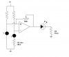
I have a 741 op amp with two voltage dividers on the + & - inputs. On the ground side of the dividers I have thermistors. They're the same except that the + side divider has a 330 ohm "offset" resistor to raise the + input up a bit even when temps are equal. This is to ensure that the output of the op amp remains off when temps are close.
To test this I tape both thermistors to a common surface so they're kept at the same temp. Voltages then are as follows
Neg level is 3.2
Positive is 3.0 V
Output is 1.3 V
The - thermistor is warmed by touching it, which causes the - input voltage to go lower than the + level. Output of the op amp goes to 5.2V and LED glows. This is what I want, and I'd expect the LED to go back off when the temps equalize as they were prior.
Trouble is the output never goes back off even when the temps normalize. I'd expect that the - & + levels would go back as they were if the temps of the surface they're attached to hasn't changed.
I can ground the + input so its level falls below that of the -. The LED will then go off and stay off.
I can also "force" the output off by warming the other thermostat and driving it voltage well beyond the opposite input.
What seems to be happening is that when the output goes high it raises the level of the + input above that of what is being represented by the ambient temp. With this "additional" voltage hanging around on the + input the - input level can never catch up, so the circuit is in effect locked. Grounding the + and dropping the output brings all levels back to normal.
Can anyone suggest a fix?
Thanks!
")
