I am hoping for help to design a simple circuit. I am not an engineer, so bear with me.
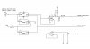
The circuit has two inputs. The first is a 0-5vdc sensor, and the second is a switch that toggles between +5vdc and ground. When the switch is set to 5vdc, I want the circuit to act as a straight voltage follower for the full 0 to 5vdc sensor range When the switch is set to ground, I want the circuit to act a voltage follower up to 1vdc, with any sensor signal over 1vdc creating a 1vdc output from the circuit. I'm hoping there is a single chip that can be used to do this? Suggestions/tips?
The circuit has two inputs. The first is a 0-5vdc sensor, and the second is a switch that toggles between +5vdc and ground. When the switch is set to 5vdc, I want the circuit to act as a straight voltage follower for the full 0 to 5vdc sensor range When the switch is set to ground, I want the circuit to act a voltage follower up to 1vdc, with any sensor signal over 1vdc creating a 1vdc output from the circuit. I'm hoping there is a single chip that can be used to do this? Suggestions/tips?
") ):
):")