Electro Tech is an online community (with over 170,000 members) who enjoy talking about and building electronic circuits, projects and gadgets. To participate you need to register. Registration is free. Click here to register now.
Welcome to our site! Electro Tech is an online community (with over 170,000 members) who enjoy talking about and building electronic circuits, projects and gadgets. To participate you need to register. Registration is free. Click here to register now.
I cannot make this circuit work. Please help. I took the circuit idea from a comparator WEB tutorial (that probably I did not undestood). The LED must turn on when I connect +5V to point A. Should it?
Thanks but I believed the LED is correctly oriented as it is. Anyway I change its orientation an it remain on all the time (even without any reference voltage).??? Any ideas??
Thanks but I believed the LED is correctly oriented as it is. Anyway I change its orientation an it remain on all the time (even without any reference voltage).??? Any ideas??
Thanks but I believed the LED is correctly oriented as it is. Anyway I change its orientation an it remain on all the time (even without any reference voltage).??? Any ideas??
Blueroomelectronics thanks for the reply.
Can you check the circuit diagram and tell me the correct connection of the LED? I try by connecting it the other way and it stay led all the time (even without the reference voltage or input voltage). I have seem many circuits on the web for comparator and the LED is always connected backwards???? This really confused me.
ericgibbs -> thanks eric . Pin 5 is the reference voltage (2.5 V) . Pin 4 is the input voltage, 5 volts in this case. Pin 2 is the output. So in this scenario the led must turn on when Pin 4 received the 5 volts.
ericgibbs -> thanks eric . Pin 5 is the reference voltage (2.5 V) . Pin 4 is the input voltage, 5 volts in this case. Pin 2 is the output. So in this scenario the led must turn on when Pin 4 received the 5 volts.
Thanks
hi,
When pin 4 goes higher than +2.5V the output will go low and the LED will light.
Try connecting pin 4 to about +3V, rather than directly to +5V, some comparator input/outputs will misoperate at voltages close to their supply voltage.
Mikebits - thanks.
I will try that when I get home. The pull up will be from pin 2 to 5v and the LED will be tied to pin 2 and ground. Correct ? (This is very different to the circuits I have seem on the web and also on a very old radio shack F.Mims book I have.)
Thanks again.
Mikebits - thanks.
I will try that when I get home. The pull up will be from pin 2 to 5v and the LED will be tied to pin 2 and ground. Correct ? (This is very different to the circuits I have seem on the web and also on a very old radio shack F.Mims book I have.)
Thanks again.
Is it possible that the circuit is breaking into an oscillation when the voltage is removed from pin 4. When the 5v jumper is pulled away, the pin 4 is left floating into a Wide band high gain circuit. Maybe a cap on pin 4 to ground would help??? What do ya think?
I think it is safe to say then that a floating input is not a good idea; ergo, some impedance needs to be on the input with or without the jumper. I would say small series R with a 5k or so shunt (to ground after series R) on the input. Here is a pic of what I am thinking.
Data sheet recommends less than 10K impedance on inputs for stability. This should give a good solid 0v while wire is float. Comments?
hi Mike,
My comment about the addition of the resistor to ground is how it would affect the driving source.
If the driving source was a 'high' impedance the 5K would load it.
The original circuit the OP posted should work, I agree that a floating input is not a good idea with most ic's.
Problem is we are seeing the circuit in isolation, how is he going to use it.?
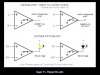
Comparators are very simple to use, if you can remember which way round they go. The attachment from Paisley tells it all. I usually used the minus input for reference, applying my signal to the plus input. It seems to work better that way.
This site uses cookies to help personalise content, tailor your experience and to keep you logged in if you register.
By continuing to use this site, you are consenting to our use of cookies.