Electro Tech is an online community (with over 170,000 members) who enjoy talking about and building electronic circuits, projects and gadgets. To participate you need to register. Registration is free. Click here to register now.
Welcome to our site! Electro Tech is an online community (with over 170,000 members) who enjoy talking about and building electronic circuits, projects and gadgets. To participate you need to register. Registration is free. Click here to register now.
Why do teachers post questions that have impossible numbers?
The saturation voltage of a lousy old 741 opamp is no where near as good as 98% and is really only 72% in this circuit which should be taught and learned.
Haha, I will take that one to my teacher. But unfortunately even with the clue Im still baffled. Ive tried reading about it but my text book doesnt cover it. Any further insight?
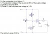
The output of this opamp is two complimentary darlington transistors. They saturate with a loss of about 1.2V without a load and with a loss of 2.5V with a 9mA load.
The question says the opamp has only a 2% saturation voltage loss so the output high voltage is 98% of 9V. Calculate it.
The output high voltage feeds the LED through the current -limiting resistor.
You know the calculated output high voltage from the opamp and you know the voltage of the LED so then subtract the LED voltage from the output high voltage of the opamp to determine the voltage across the current-limiting resistor.
Then use Ohm's Law to calculate the value of the resistor.
Easy.
The optimum value is infinity, or an open circuit, so that the LED does
not burn out due to reverse overvoltage when the op amp switches
its output toward the negative supply which is -9v. Many LEDs can
not take this much voltage
If you ignore that, then yes you first need to calculate 98 percent of
9 volts and then subtract the LED voltage and calculate the resistor
using Ohms Law.
This site uses cookies to help personalise content, tailor your experience and to keep you logged in if you register.
By continuing to use this site, you are consenting to our use of cookies.

")