I am trying to use a comparator that will switch when the reference voltage drops below 6V.
The voltage I want to trigger this is the voltage between the test points (not between the test point and ground.)
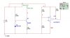
I have attached a picture of my latest circuit and a zip of it in multisim any help will be greatly appreciated.
The voltage I want to trigger this is the voltage between the test points (not between the test point and ground.)
I have attached a picture of my latest circuit and a zip of it in multisim any help will be greatly appreciated.
")
