Continue to Site

Welcome to our site!

Electro Tech is an online community (with over 170,000 members) who enjoy talking about and building electronic circuits, projects and gadgets. To participate you need to register. Registration is free. Click here to register now.

  • Welcome to our site! Electro Tech is an online community (with over 170,000 members) who enjoy talking about and building electronic circuits, projects and gadgets. To participate you need to register. Registration is free. Click here to register now.

Comments Sought on Proposed Plasma Signal Mixing Tube

Status
Not open for further replies.

digimax

New Member
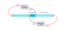
The attached diagram shows a concept for signal mixing within a plasma tube. I am looking for comments regarding its viability in terms of electrodynamics and hardware design. The voltages shown are intended to relate to an ordinary fluorescent tube after triggering.

I would also appreciate suggestions on the simplest way to generate 100VAC audio frequency signals with the differing DC offsets as illustrated below.

plasma_mixing_tube.png
 
"100V line" transformers for the high voltage audio, connected to the outputs of a suitably powerful audio amp.

You would need DC power supplies at the various bias voltages with series current limiting resistors (in both connections to the red leads) , then capacitor couple the transformers at one side of each transformer to prevent them shorting the bias voltages.

Whether it would work or not is another thing. For experience trying to use fluorescent tubes as giant strobe tubes, once the ionisation builds up they will conduct quite easily & the ionisation takes a significant time to dissipate.

Edit- typo
 
Last edited:
Attached some HV booster stages.


Regards, Dana.
 

Attachments

  • Op_Amp_Booster_Stages_pt1.pdf
    8.1 MB · Views: 214
  • Op_Amp_Booster_Stages_pt2.pdf
    2.7 MB · Views: 199
Thanks for the replies so far.

I have a pair of generic 100V PA line matching transformers that I can drive via their 8 ohm primary with a spare stereo Hi-Fi amp.

There are two bias voltages shown in my diagram above. One is -20V and the other -100V. The block diagram below shows my interpretation of rjenkinsgb's suggestions. Any corrections would be welcome please. Given the voltages specified, what would be recommended values for the resistors and cap?
dc_biased_signals.png

I have applied HVAC to fluorescent tubes before. Given low frequency they will flicker but not "strobe". However, the purpose of the present exp is the mixing effect at the center of the tube. Any comments on what might happen there?
 
That does not provide the 200V across the tube ends, also the cap there is shorting the centre input signals at audio.

It also relies on independent, totally floating DC power sources. If you are using those, then this is nearer the target:

Fluro_tube_dc_biased_signals_2.png


My original basis was having all supplies referenced to a common 0V, so 80V, 120V & 200V DC, so no floating supplies needed.
Each would have its own smoothing, with series resistors to the tube ends from the 0V and 200V point.

The version I first described was to have the 80V and 120V points connected to the tube as well, then using capacitive coupling with each transformer secondary having a series DC isolating capacitor and connected to the tube terminals (after the limiting resistors), across the points in your original diagrams.

A simpler method would be to put the 100V line transformer secondaries in series with the 80V and 120V feeds to the tube, to apply the modulation superimposed directly on those voltages.

Fluro_tube_dc_biased_signals_3.png
 
Thank you for correcting my diagram. I looked at your simpler version but it does not seem the same as my original proposal which has +/- HV to the tube ends. IOW there is no 0 voltage on the secondary side. The electrostatic "balance" may be important to achieve the effect I am after within the mixing region.

The original plan was to use two dual rail bench power supplies.

However, I have redrawn the diagram incorporating your most recent suggestion, as I understand it. Any further comments would be most welcome.
signal_modulation.png
 
The 0V in my drawing is a reference point and does not have to be a literal ground, if you are using floating PSUs; just be sure they are rated for the required voltage between outputs and ground.

To set the centre of the tube as near actual ground as possible, add two equal resistors between the +80V and +120V PSU outputs, with a cap across one or both so capacitive leakage currents do not vary the voltage, and ground the mid point.

That then makes the voltages to ground -100, -20, +20 & +100.

That general approach avoids having the high voltage audio signal across the PSU input <> output or output <> ground, where it could be affected by internal filtering
 
Sorry, but I am getting a bit lost in the descriptions.

However, it occurred to me that there may be a simpler way that does not require biasing power supplies.

Feed the same signal into two transformers, each of which has a center tapped secondary. Ground the center tap of both windings, in common with the stereo push/pull type amp.

Drive one end of the tube from the high side of one transformer's secondary, and the other end of the tube from the low side of the other transformer. The signal voltage on each would then be swinging - and + 100V respectively.

Then connect the positive-going signal to the middle electrode that is farthest from the negative end of the tube, and do conversely for the negative-going signal. Use a resistive divider to reduce the voltage on each to something like 50Vpp.

This would appear to create the desired "mixing region" referred to in my OP.

What do you think?
 
With two identical transformers, with centre taps connected together, the output voltages from the two will be identical. It makes no difference voltage-wise which of the two you connect to.

This is what I was meaning:

Fluro_tube_dc_biased_signals_5.png
 
Now I understand. Thanks.

Here is a diagram of what I had perhaps not described clearly one post back. Maybe review that now.

The signal input would be bipolar, and square for maximum induction. Transformers probably split 120V to 3V(??) wired in backwards for step up. Dashed rectangle is the tube.

Apologies for the blurry image. It's a long story. I think you will get the idea anyway. I would appreciate your expert opinion on same.

fluorescent_tube_driver.png
 
That's what I thought you meant.

With the primaries fed from the same signal and the secondary centre taps linked, the voltage at the dotted end of the two transformers will be identical, and the voltage at the lower end identical.

It's no different to using both ends of one transformer secondary.

However you have lost me on the overall concept - I thought the idea was to have a permanent feed across the tube ends & then two different audio signals fed to near the centre, to see the result of the frequency mixing? Though I may it totally wrong!
 
The secondary voltages are anti-phase to each other thereby creating an alternating potential across tube ends.

You are right about needing only one transformer. The second one is leftover from another idea that used both channels of a stereo amp.

What I am attempting to create is two "tubes" within a tube, with an overlapping region of destructive interference. For this to work, the middle two electrodes, acting as returns, must be at lower voltage so the opposing potentials enter the mixing region.

That is what I had intended to show in my diagram at the top of this thread. If this can be done with a transformer, with resistive dividers to the center electrodes, that would be my preferred approach.

I would like to nail this down, both in theory and implementation, so I can start building with some degree of self-confidence.
 

Attachments

  • plasma_mixing_tube.png
    plasma_mixing_tube.png
    19.4 KB · Views: 168
Fluorescent Tubes run off high voltage and low current. A rapid start 4ft tube can be 30W +/- 4W depending on type. Both end pins are shorted as there is no heater in these modern tubes. The yellow wires are common in multi-tube (eg dual or quad) ballasts and any number can run without a dependence on the other tubes being connected or working. So you will need an audio power amp to power this with a booster. The output brightness is controlled by current and has a decay time.

Your transformer is just a differential medium impedance output with a common mode resonance that is high impedance.

I think you should just experiment with drivng a tube with two automotive autotransformers to drive each end with a differential output of a stereo amplifier and overvoltage protection. The destructive interference you are looking for may occur with phase shifts of filtering one side of the mono sound and the stereo separated sounds ought to be ignored with the primary phase inverted rather than common ground.
 
I generally use a small fluorescent tube from a camping lantern. This allows for commonly available PA or power transformers. Getting it to ignite is not a problem.

The primaries are common ground to create a voltage difference at the tube ends via anti-phase signals. Tony seems to be suggesting an alternative way using stereo signals, although I am not sure of the reason for this.

I have not seen any comments here (so far) that my most recent diagram would not work. Note that it does not show the divided lower voltages to the middle electrodes. Maybe it is time to hit the bench and give it a try.
 
I've got totally lost as to the aim of your project....

Your first post said "Signal mixing". That by definition means two different signals, but your later posts use a single common feed.

It appears you could get the same effect as your last circuits with an original fluorescent fitting or lantern, just by adding link wires from a pin at each tube end, to conductive bands added to the tube just past centre from each side?
 
The first diagram I posted employed the one signal with two different offsets. I used the term "mixing" because the result, in terms of dynamics, is two versions of the original.

The discussion then moved on to achieving a similar effect without the necessity of HV power supplies. This used step-up transformers and phase inversion, with lesser voltage applied to the middle plates via voltage dividers.

Yes, it's another strange project, but I now have a better idea of where it is headed. My apologies for any confusion.

You are certainly right about using the lantern "as is" but frequency is then determined by the onboard oscillator, not the LF source I had in mind. Might make a good preliminary test though.
 
I ran your recent circuit in similation. I couldn't control any plasma current so I used caps. Nothing revealing.

You don't need a centre tap and it is differential output but turns ratio and impedance ratios will matter. As I said, mono sounds will add and stereo sounds will subtract with the inversion. Common mode secondary voltage can be very high over the differential voltage. You can probably modulate the current with just step up autotransformers with windings around each tube end to modulate the current in mono. I would expect lower frequencies to be more responsive. I've used a car ignition coil up 10 kHz to trigger a ESD gas tube to glow. They react like Triacs but scaled up in voltage and low trigger currents I forget , but I think the transformer turns rato was 100.

If the tune lamp is operating, all you need is low voltage induction current to modulate the light. not high voltage., so imagine like driving stereo speaker coils wrapped around the tube ends..
 
Last edited:
What is the output of this “mixing”?
Electrical, audio or visual?
This is an experiment I played with a while ago.
 
Tony's first simulation demonstrates sinusoidal voltages of alternating polarity created by the split secondary method used in my most recent circuit above. All that needs to be added are the two middle electrodes that sit at lesser voltages and are staggered in polarity so the two opposing currents interfere or "overlap".

The second simulation shows classical standing waves. While interesting, my original concept was for audio signals, and the effect would not be as much frequency-dependent.

I have a singing Tesla coil I purchased online, but that approach would not be as controllable in terms of frequency makeup and voltage out.

The purpose of my experiment is to produce an unconventional type of standing wave that is independent of wavelength.
 
Status
Not open for further replies.

Latest threads

New Articles From Microcontroller Tips

Back
Top