Electro Tech is an online community (with over 170,000 members) who enjoy talking about and building electronic circuits, projects and gadgets. To participate you need to register. Registration is free. Click here to register now.
Welcome to our site! Electro Tech is an online community (with over 170,000 members) who enjoy talking about and building electronic circuits, projects and gadgets. To participate you need to register. Registration is free. Click here to register now.
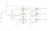
i am doing a project on colour sensor. the attachment is a schematic of my project but the output is unstable and i cant figure out how to stabilize it... need help... urgent..
If the op amps are LM324, the common mode range does not include the positive supply. You have the noninverting inputs connected to VCC, which is outside the common mode range. With the other end of your photodiodes also connected to VCC, their capacitance will be higher than if you had them reverse biased. High capacitance on the inverting input can lead to op amp instability (when you get your op amps biased correctly).
This site uses cookies to help personalise content, tailor your experience and to keep you logged in if you register.
By continuing to use this site, you are consenting to our use of cookies.