Electro Tech is an online community (with over 170,000 members) who enjoy talking about and building electronic circuits, projects and gadgets. To participate you need to register. Registration is free. Click here to register now.
Welcome to our site! Electro Tech is an online community (with over 170,000 members) who enjoy talking about and building electronic circuits, projects and gadgets. To participate you need to register. Registration is free. Click here to register now.
Color organs have filters for different frequencies. Yours doesn't have a filter.
1) The input should have a coupling capacitor but it must be huge because the first opamp is inverting with a very low input impedance.
2) Why do you have the second opamp? Its voltage gain without feedback is 200,000.
The trimpot should be connected to the first opamp and remove the second opamp then drive the TTL inverters from the first opamp.
3) The typical output low voltage of the LM358 opamp is barely low enough to be a valid logic low for the TTL inverters.
4) The output high voltage and current from the TTL inverters probably is not high enough to activate the MOC triac drivers.
Get rid of the inverters and connect the resistors feeding the MOC triac drivers directly to the output of a single opamp.
To use a microphone then you should make a low-noise mic preamp to match the type of mic you will use. Since you cannot see hissss from the lights then the extra opamp in the LM358 can be used as a preamp.
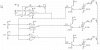
Here is my idea for the circuit without a mic preamp:
but i have another disgen, which works very will coz i was using UBS -conected to my computer , but when i connected it to another PC's ......... Spark and some smoke around..............hhhhhhhhhhh
if its possible to change the input to work with mic ....i think it will solve something ....i didnot use a triac coz its very expensive in my case
Your new circuit does not have opto-triac-drivers so it is extremely dangerous and could easily electrocute somebody.
Depending on how the power receptacle or computer's power cord is wired then the computer could be connected directly to 220VAC through your circuit. Maybe the spark blew up part of your circuit's ground or nuetral wiring.
Your new circuit shows a normal opamp at the top with a voltage gain of about 30. Then its output drives two opamps without negative feedback so their gain is about 200,000.
Your new circuit does not have opto-triac-drivers so it is extremely dangerous and could easily electrocute somebody.
Your new circuit shows a normal op amp at the top with a voltage gain of about 30. Then its output drives two op amps without negative feedback so their gain is about 200,000.
I think if i could have a microphone it will be safe become its not like speakers" My opinion" after that if i can connect a mic in right way i don't need to isolate the circuit "the problem that i have the PCB but i'm trying to make it work if there is no way i will make another one "
you could see the PCB on youtube link its clear i will paste it again https://www.youtube.com/watch?v=EW8mAfC0PuA
and for the negative feedback i put an inverter but its not shown in the schematic .
if this schematic is fail and i could not make it valid can you suggest another one make the same function for AC lamps or 12 volt DC work with microphone
as your opinion
im searching on the internet about something to add it my my circuit , i see most of your post about color organic,put im afraid to start again from the beginning "i dont have time"
Sorry for bumping this, but it's not that old... I don't think...
I was just taking a look at the colour organ segment of the "mood light", and I was wondering whether I would be able to take the filter outputs directly to say a One Shot and then to a FET/SCR to drive LEDs or Globes?
This site uses cookies to help personalise content, tailor your experience and to keep you logged in if you register.
By continuing to use this site, you are consenting to our use of cookies.

 Spark and some smoke around..............hhhhhhhhhhh