Continue to Site

Welcome to our site!

Electro Tech is an online community (with over 170,000 members) who enjoy talking about and building electronic circuits, projects and gadgets. To participate you need to register. Registration is free. Click here to register now.

  • Welcome to our site! Electro Tech is an online community (with over 170,000 members) who enjoy talking about and building electronic circuits, projects and gadgets. To participate you need to register. Registration is free. Click here to register now.

coin operated pc

Status
Not open for further replies.

harryperales

New Member
need help with coin operated pc project

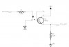
im currently in the stage of making a coin operated pc, i want to interface the coinslot using the parallel port. my problem now is that the coinslot gives a 12v 50ms pulse, which is the source of all my trouble because in order for it to be parallel port compatible it has to be converted into a TTL signal, can any one help me find a way in converting this signal into parallel port compatible.

i already have a software that pools the parallel port for a signal from the coinslot signal and unlock the pc when a signal has been detected.

any help will be greatly appreciated...
 
Last edited:
You could use a simple transistor based circuit - the 12V would drive the base of an NPN transistor whose collector is connected to 5V via a resistor and whose emitter is connected to a common ground. The parallel port pin is then connected to the resistor / collector junction. Google for 'transistor switch'.

An alternative idea is to use an optocoupler, same principle of operation but using an isolated input, which would be superior. Google optocoupler or optoisolator for details.

Even simpler is a straightforward mechanical relay circuit.

Be aware though that both transistor approaches would invert the signal you're measuring, unless you use two transistors.

since im not really very good with electronics, i was hoping that maybe you could give me a suggestion for the best opt coupler and how to make the connections...

thanks alot for your interest in helping me
 
Well as I understand it this forum is meant to be a learning resource rather than just a source of free consultancy, so in that vein I point you again to Google which will tell you what you need to know. This will benefit you in the long term especially if you are trying to get involved in things like this.

Take a look at **broken link removed** and perhaps https://www.electro-tech-online.com/custompdfs/2009/02/optocoup.pdf.

Relays are even simpler to understand and aren't electronic, they're electromechanical - maybe you would be better off going that route.
 
thank you very much for your help, i tried more googling and i found a diagram utilizing pc817 optocoupler....

thank you very very much
 
i have 1 thing i im not sure about the diagram that i found. what is the voltage rating for the C1 1nF capacitor.

**broken link removed**
 
Well, it only needs to be a 5V cap but since this is probably going to be a ceramic type you'll find that even a 10-50V rated cap will still be very small. So as long as it's 10V or higher you're in the 'safe zone'.

That's a suitable circuit though. Just be aware that when you put 12V on the input, the parallel port pin will read 0V and vice-versa.
 
thank you very much for your very quick reply. more power and god bless, you are a really big help to people who are new to electronics just like me.
 
You could use a simple transistor based circuit - the 12V would drive the base of an NPN transistor whose collector is connected to 5V via a resistor and whose emitter is connected to a common ground. The parallel port pin is then connected to the resistor / collector junction. Google for 'transistor switch'.

An alternative idea is to use an optocoupler, same principle of operation but using an isolated input, which would be superior. Google optocoupler or optoisolator for details.

Even simpler is a straightforward mechanical relay circuit.

Be aware though that both transistor approaches would invert the signal you're measuring, unless you use two transistors.

- OR - even simpler why not just a simple voltage divider... 6.8k over 4.7K??????
 
i have 1 thing i im not sure about the diagram that i found. what is the voltage rating for the C1 1nF capacitor.

**broken link removed**

The beauty of using opto isolators is that you don't have to worry about transistor base bias levels, so you can insert the collector/emitter anywhere you need to.

Here is the same circuit in non-inverting form. (I omitted the cap but I would put one across the resistor).
 

Attachments

  • opto..JPG
    opto..JPG
    26.7 KB · Views: 1,853
Status
Not open for further replies.

New Articles From Microcontroller Tips

Back
Top