Continue to Site

Welcome to our site!

Electro Tech is an online community (with over 170,000 members) who enjoy talking about and building electronic circuits, projects and gadgets. To participate you need to register. Registration is free. Click here to register now.

  • Welcome to our site! Electro Tech is an online community (with over 170,000 members) who enjoy talking about and building electronic circuits, projects and gadgets. To participate you need to register. Registration is free. Click here to register now.

Coil Circuit and Velleman Transistor Ignition Kit

Status
Not open for further replies.

sign216

Member
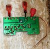
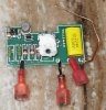
I added a Velleman transistor assisted ignition kit to a 1965 Benelli/Wards Riverside motorcycle ignition circuit. But with the added ignition kit, the connectors for the coil+horn on the circuit board heat up and start to smoke! And there's no spark at the plug.

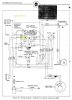
The motorcycle circuit is a little strange, in that the coil+horn looks like there's a direct connection to the battery, bypassing the main fuse! Why would they do that?

What could possibly be going on to cause the hot junction ? Attached is the Velleman manual, highlighted on page 7 where it talks about ballast resistor. Should I add one?
Also attached is the motorcycle wire diagram, highlighted to show the ignition switch, which connects as soon as the key is inserted.

Any help at all is appreciated. I'm a better cyclist than I am an electrician.

Joe
 

Attachments

  • Velleman Ignition Kit - highlighted pg 7.pdf
    339 KB · Views: 208
  • Wire Diagram - ignition switch highlighted.jpg
    Wire Diagram - ignition switch highlighted.jpg
    436.9 KB · Views: 351
If you have connected the unit up as shown in the diagram in the manual then the current into pin 1 should be no more thatn about 300 mA with the contact breaker in the closed position and even if T1 had a collector emitter short. Show us a schematic of how YOU HAVE WIRED the unit and also a picture of both sides of the board so we can see if you have shorted any tracks out with bad soldering. With the board NOT connected measure the resistance between pin 1 and pin 2 and also between pin 1 and pin 4.

Les.
 
Les,
Attached are pics of the unit, without the heat sink.
Also attached is a diagram of the kit connections to the bike. The only difference I made, was connecting the lead from 1 directly to the coil (+). Since it's closer than the ignition switch, and the ig switch should be just a wire going straight to coil (+).

With the kit disconnected,
between 1 and 2 I get 75 ohm
between 1 and 4 I get no ohms.

Should I add a ballast resister to the coil (+) to limit current? The kit doesn't call for it, but it might be an answer (in my heart, the kit should work as designed, without it).

I thank you for help, as this board is my only hope of figuring this out.

Joe
 

Attachments

  • SDC15431.JPG
    SDC15431.JPG
    317.2 KB · Views: 269
  • SDC15432.JPG
    SDC15432.JPG
    279.3 KB · Views: 345
  • Page 6 From Velleman Ignition Kit.PDF
    21.6 KB · Views: 193
  • Wire Diagram - ignition switch highlighted.jpg
    Wire Diagram - ignition switch highlighted.jpg
    436.9 KB · Views: 269
Ignit.jpg

From this image, marks seem to show there was a washer over the mounting hole. If metallic, it could have shorted to track areas 1 or 2.
Check for solder splashes at the heads of arrow 2 and the non-numbered arrows.
 
Hi Alec,
Well spotted. I had not noticed the mark from a large washer. That would explain the large current if the transistor mounting screw was also being used to bolt the board to ground but it would not explain the zero ohm reading between pins 1 and 4 with the connections removed. I could see no solder splashes that would explain this short. (I am starting to think that when Jo said "no resistance" he means infinite resisance rather than zero resistance.)

Les.
 
I am starting to think that when Joe said "no resistance" he means infinite resistance rather than zero resistance.
He wouldn't be the first to express it that way :).

Edit:
Googling "velleman transistor ignition schematic" seems to bring up the schematic for the module.
I don't have much faith in that Riverside wiring diagram (if I'm interpreting it correctly). The only supply to the ign coil primary seems to be via the horn button or via the generator indicator bulb ??
 
Last edited:
Those two 'plates' inside the yellow/green rectangle.... I think that is a mechanical switch that is open when the main switch is 'off' and closed when the main switch is 'on'. That would get power from the regulator B+ through the fuse, or from the battery via (looks like) '30' on the switch.
 
Good eyes. The circular marks are from a nylon screw that goes through the unit, holding the transistor to the metal container lid, that I'm using as a heat sink. There's a mica film shielding the transistor from the lid. I'll try the unit again, without the metal container, in case the container is shorting the unit.

Alec and Les, you're right, I meant infinite resistance, not zero resistance.

Thanks for pointing out the solder splashes. Most of them are actually marks in the board's resin surface and not solder. I verified w a multimeter that there's no continuity between the "arrowed" pins.

Alec, the bike's diagram is hard to read. I high-lighted the ignition switch in yellow, which is closed as soon as the key is inserted. It's easier to view the coil's power path by following backwards from the battery. Oddly, the coil and horn get power directly from the battery, bypassing the main fuse. Without the transistor unit, there's no problem. But adding the transistor unit, and the coil+horn get too much power and heat up almost to smoke, before I pull the switch.

Is it possible that the transistor unit is giving the coil+horn a new ground, that allows the current to run?


P.S. The only error I've found in the bike's wire diagram (and it's not relevant (I think)) is the black wire from the Emergency Bypass Switch to the Regulator Df point. That's incorrect, it actually goes to the Regulator ground. The Emer. Bypass allows the bike to be started w a dead battery, by removing the battery and connecting the coil to the generator. You push start the bike then.
 
Those two 'plates' inside the yellow/green rectangle.... I think that is a mechanical switch that is open when the main switch is 'off' and closed when the main switch is 'on'. That would get power from the regulator B+ through the fuse, or from the battery via (looks like) '30' on the switch.

Ylli, thanks for pointing that out. I didn't notice that before. It does show that the coil is connected to the generator (and ultimately the battery) at a second point, but the power then has to pass through the hi-beam indicator light. I don't understand why. If it helps, when the transistor unit is on the bike and powered up, this high beam light glows mildly.

Strange.
 
Sign, JOOC, what are you expecting to gain by using this circuit? In the original configuration, you are switching the coil current on and off with a mechanical switch. With the box, you mover that function over to a transistor, but you are still using the mechanical switch (points) to determine the timing. The only thing I see you might gain is increase life of the points.

To me it is like using a motor to drive a generator to drive a motor. No functional gain, just added complexity.


According to the instructions, if there is a ballast resistor, the power for the board needs to come before the resistor - basically any ballast resistor needs to be bypassed. If you are making all you connections at the coil/points, then I don't see how you can be affecting the horn circuit. And the coil should not /can not be drawing any more current than if the motor was stopped with the points closed. Double check the way you are connecting the unit.
 
Have you made sure that the primary coil is not grounded to the bike chassis by its mounting/casing?
 
Sign, JOOC, what are you expecting to gain by using this circuit? In the original configuration, you are switching the coil current on and off with a mechanical switch. With the box, you mover that function over to a transistor, but you are still using the mechanical switch (points) to determine the timing. The only thing I see you might gain is increase life of the points.

To me it is like using a motor to drive a generator to drive a motor. No functional gain, just added complexity.


According to the instructions, if there is a ballast resistor, the power for the board needs to come before the resistor - basically any ballast resistor needs to be bypassed. If you are making all you connections at the coil/points, then I don't see how you can be affecting the horn circuit. And the coil should not /can not be drawing any more current than if the motor was stopped with the points closed. Double check the way you are connecting the unit.

Alec, thanks for that idea. I checked w a multimeter, and the coil housing is correctly isolated from the bike's body.

Ylli, I'm hoping to gain;
1. Increased points life. The points are buried behind the engine casing, under the generator, and not as accessible as most vehicles.
2. I'd like to increase spark too. There's debate about whether transistor assisted ignition lives up to this claim, and I must admit the claim is probably spurious.

I'm going to try the unit again w the horn disconnected, and without the trans. unit's metal housing, to eliminate those as issues.

Joe
 
Sign, JOOC, what are you expecting to gain by using this circuit? In the original configuration, you are switching the coil current on and off with a mechanical switch. With the box, you mover that function over to a transistor, but you are still using the mechanical switch (points) to determine the timing. The only thing I see you might gain is increase life of the points.

To me it is like using a motor to drive a generator to drive a motor. No functional gain, just added complexity.


According to the instructions, if there is a ballast resistor, the power for the board needs to come before the resistor - basically any ballast resistor needs to be bypassed. If you are making all you connections at the coil/points, then I don't see how you can be affecting the horn circuit. And the coil should not /can not be drawing any more current than if the motor was stopped with the points closed. Double check the way you are connecting the unit.
.

Ylli,
Another reason I added the transistor unit is to reduce the engine's idle speed.
Yes, I know, it doesn't make sense, but I'll start a new thread on that point.
Joe
 
After testing, it appears that the issue is the unit grounding out against the metal enclosure I put it in.
This isn't complicated, so I think I can properly isolate it.

Sorry to have to ask for help on what turns out to be a construction error, but the oddities of the bike's electrical system made it hard to diagnose.
I mean, what vehicle powers the horn and the coil on the same circuit, and also bypasses the main fuse to do it. Makes no sense.
Later I'll add a fuse to that circuit, just to protect things.
 
Status
Not open for further replies.

Latest threads

New Articles From Microcontroller Tips

Back
Top