Continue to Site

Welcome to our site!

Electro Tech is an online community (with over 170,000 members) who enjoy talking about and building electronic circuits, projects and gadgets. To participate you need to register. Registration is free. Click here to register now.

  • Welcome to our site! Electro Tech is an online community (with over 170,000 members) who enjoy talking about and building electronic circuits, projects and gadgets. To participate you need to register. Registration is free. Click here to register now.

CMOS homework... please help

Status
Not open for further replies.

latvian

New Member
Hello everyone,
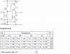
I have this question in my homework that I am having problem solving it. The question is a CMOS network of gates that I must give the truth table of it and to choose the type of the network.

The choices for the y are: 0, 1, z

The choices for the type of network is: tri-state inverter, tri-state buffer, AND network, OR network, NAND, NOR, XOR, XNOR.

The question is attached with this question as a screen shot image...

Please help!

Thanks in advance
 

Attachments

  • namnlös.JPG
    namnlös.JPG
    38.3 KB · Views: 591
Hi,

If you follow the transistor logic, when certain transistors turn on others turn off, and this leads to the solution that it must be a tri state inverter. You should be able to find this solution yourself too though by following the transistor conduction paths.
There are only four possibilities for the inputs A and B, 01, 10, 11, or 00. If you look at what the output would be for all four of these input conditions you should be able to trace it out. Try it and see.
 
Last edited:
Hi,

If you follow the transistor logic, when certain transistors turn on others turn off, and this leads to the solution that it must be a tri state inverter. You should be able to find this solution yourself too though by following the transistor conduction paths.
There are only four possibilities for the inputs A and B, 01, 10, 11, or 00. If you look at what the output would be for all four of these input conditions you should be able to trace it out. Try it and see.

I know that in a tri-state buffer, there is a controlling signal. That's to say if that signal is 0 then the output would be z then the output would follow the other input signal. Let's call the controlling signal xSo the truth table for the tri-state buffer would look something like that:

x y f
0 0 z
0 1 z
1 0 0
1 1 1

I think in my question, A is the controlling signal but I am not really sure how the truth table would look like!
 
Hi again,


In your diagram, A is the controlling signal controlling the tri state state. B is simply an inverter so the input B to output is:
0,1
1,0

Note that when A is low N2 and P2 are in the OFF state so B can not cause any output. It's only when A goes high that N2 and P2 turn on and so then B is allowed to set the output, and since B is connected to an inverter, the output is C=B' which is an inverter. Since A controls the tri state state, we have for inputs A and B and output C:
A-B-C
0-1-z
0-0-z
1-1-0
1-0-1

or
C=B' when A is high, and
C=z when A is low.

That's a tri state inverter.
 
Last edited:
Hi again,


In your diagram, A is the controlling signal controlling the tri state state. B is simply an inverter so the input B to output is:
0,1
1,0

Note that when A is low N2 and P2 are in the OFF state so B can not cause any output. It's only when A goes high that N2 and P2 turn on and so then B is allowed to set the output, and since B is connected to an inverter, the output is C=B' which is an inverter. Since A controls the tri state state, we have for inputs A and B and output C:
A-B-C
0-1-z
0-0-z
1-1-0
1-0-1

or
C=B' when A is high, and
C=z when A is low.

That's a tri state inverter.

Thank you so much for your reply and help. Now it's clear what a tri-state inverter is, although I think it's a little bit difficult.
Thanks again
 
Hello again,


Oh i see, i didnt realize you never worked with a tri state inverter before or i would have explained a little differently. Anyway, good luck with it.
 
Status
Not open for further replies.

New Articles From Microcontroller Tips

Back
Top