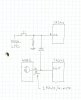
Electro Tech forum,
I'm having a problem driving the clock pin of a 74LS393N
with the output pin of a TC4082BP cmos quad and gate.
The output of the gate is just a low to high to low pulse
once a minute.
It works ok if I jumper it direct but if I replace the
jumper with a diode the 74393 doesn't clock. The diode
is a 1N4148 and I'm pretty sure it's the right way around.
I'm only driving 2 other ttl pins with this gate so
fanout shouldn't be a problem. The diode doesn't
go to these other pins.
Won't have a scope until late next week.
Any suggestions?
jerryd
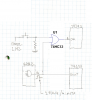
")