Electro Tech is an online community (with over 170,000 members) who enjoy talking about and building electronic circuits, projects and gadgets. To participate you need to register. Registration is free. Click here to register now.
Welcome to our site! Electro Tech is an online community (with over 170,000 members) who enjoy talking about and building electronic circuits, projects and gadgets. To participate you need to register. Registration is free. Click here to register now.
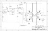
What you haqve there is a PMW generator. You control it by regulate P1.
If you want to use an external controller source, you must detatch P1, R1 and R2 and just feed voltage into positive input at IC1A. But first you have to calculate the minimum and max voltage to input.
Assuming you also have a tachometer on the motor shaft, next thing is to assemble it and run it.
so the output from the techometer (frequency to voltage converter) will go into the input of the PID controller and the out put from PID controller to the Pin 3.
so the output from the techometer (frequency to voltage converter) will go into the input of the PID controller and the out put from PID controller to the Pin 3.
if you do not need accuracy you do not need a tach... diode or the two sides of the motor together and filter out the HF component - DC motor speed is proportional to motor voltage
we use simple PWM ICs to control 100V 30A motors here... simple summing function - for a 1V summing junction you take
((0 to 5V control)/5 + (IR compensation for your motor) - (motor voltage)/24 = 1V
IR compensation is probably 20-30%. for instance our 100V 30A motors are mostly around 1 ohm armatures, so at full current they drop 30V on the resistance leaving 70V for the ideal armature... for 10% of full speed at full torque this means we need to supply 40V instead of 10V
many applications would not even need a PID loop ... BTW switching all 4 FETs every cycle is very wasteful, you should only be switching one side at a time.
R1 ,R2 & P1 determine your PWM ... delete half the bridge and ground that side of the motor
what is your PID loop in? the over complicated circuit is to prevent the transistors from being on at the same time and i think (with out doing any calculations) is why you are having trouble. if a micro you are better off using its PWM directly and external delays (if it is not a real motor chip that has non overlapping PWM outputs) to prevent the transistors from being on at the same time... or simply put a fast diode across the motor with a single FET
This site uses cookies to help personalise content, tailor your experience and to keep you logged in if you register.
By continuing to use this site, you are consenting to our use of cookies.