AcousticBruce
Member
When I looked at this I said... hmm R1 must be shorted. Makes sense to me.
I cant see any other way.
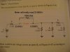
The book says the most probable failure is R2 is open?!? How is this? If R1 is fine, shouldn't it be a little less than 24v? Doesn't the 3.3kΩ take some of the voltage away?
**broken link removed**
How is this 24V???? The ground of the current still has to travel through resisters to get to the voltmeter ground.
**broken link removed**
I cant see any other way.
The book says the most probable failure is R2 is open?!? How is this? If R1 is fine, shouldn't it be a little less than 24v? Doesn't the 3.3kΩ take some of the voltage away?
**broken link removed**
How is this 24V???? The ground of the current still has to travel through resisters to get to the voltmeter ground.
**broken link removed**
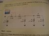
") both sides of R1 are at the same potential, since no current is flowing.
both sides of R1 are at the same potential, since no current is flowing.
")