Continue to Site

Welcome to our site!

Electro Tech is an online community (with over 170,000 members) who enjoy talking about and building electronic circuits, projects and gadgets. To participate you need to register. Registration is free. Click here to register now.

  • Welcome to our site! Electro Tech is an online community (with over 170,000 members) who enjoy talking about and building electronic circuits, projects and gadgets. To participate you need to register. Registration is free. Click here to register now.

circuit separator / circuit isolator IC?

Status
Not open for further replies.

Tiger555

New Member
Hi,

I have an input going to 8 differential op-amps circuits. On each op-amp it attenuates from 12v to 1v,2v,3v,4v etc..

To attenuates, I am using a resistor in series 2.7K and a 1k in parallel.

Since I share the same Inputs to all the 8 Op-amps, the voltage is distributed and also going to ground..

So I want to separate all inputs.. so it coud be fine..

What I am looking for is an IC that can separate. So I can feed one to each.. from the common Input.. Hope you got the idea..

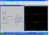
please see a sample for just 1..

Circuit Simulator Applet

I tried changing the 2.7k and 1k to 270k and 100k. but i have to get a microsec pulse.. thats missing when i did that...

And as i read a feedback opamp will do.. but its again opamp to another opamp is there something simpler??

Thanks in advance..

Cheers
 
Hi,
Thanks. But that will not work.

Explaining the circuit..

12V input varies from 0 to 12V depending upon the pulse size
1V is the noise that too varies

so the second circuit is just for to take pulse above 4V - the noise
so i did an attenuation... i.e when the pulse is above 4v that opamp will work..

I have the same for another 6 to 8 circuits

in realtime the pulse and the noise is from the same line... so the same line is going in all the op amps.. and since i ground for the atten.. the voltage drops..

so i am looking for something that can entirely.. differ each circuits..

hope now you got it..

Thanks in advance
 
So you are trying to detect a short pulse with varying amplitude and varying amounts of noise, is that correct?

What is the repetition rate of this pulse?
 
Hi,

Yes... The pulse are in micro sec... and it will repeat when there is a defect (hole detector in textile making industry) so that repeat ion is not constant..

now I plan to go ahead like this..

a feedback op amp, voltage divider and then diff op amp for noise to signal...

But I still look for something that isolate a single line.. so i can use that in diff places..

may be a chip thay contains just in- out

or just one in and many out..

so that isolates the signals..

cheers


So you are trying to detect a short pulse with varying amplitude and varying amounts of noise, is that correct?

What is the repetition rate of this pulse?
 
You could amplify the signal with a buffer amp, if needed, to drive several additional amp in parallel.

But I fail to see how having several amps looking at the same signal will help in detecting that signal (?). How will you determine which output is the desired output?
 
I'm not sure if it is your simulation or the circuit that is giving you trouble.. But if you look at the schematic it appears your op amp is using 5 volts. If so when the signal goes above 5 volts (like the top op amp) it won't work. Also not just every op amp will give a 1 Usec. pulse from ground to 5 volts, so maybe you will use a high speed comparator? Maybe you could add another set of op amps to your schematic so we can see the different steps? What do you do with the outputs?
 
Hello there,

Simu is just a demo.

As I said, I have noise and along with that I have pulse coming once in a while. The pulse voltage size determines the classification. thats why I am classification separating.. each..
Out out is merged.. to get a single voltage.. that determines the classification.. among 8.
Circuit Simulator Applet

I have a diff circuit that amp the noise to 5X.


I'm not sure if it is your simulation or the circuit that is giving you trouble.. But if you look at the schematic it appears your op amp is using 5 volts. If so when the signal goes above 5 volts (like the top op amp) it won't work. Also not just every op amp will give a 1 Usec. pulse from ground to 5 volts, so maybe you will use a high speed comparator? Maybe you could add another set of op amps to your schematic so we can see the different steps? What do you do with the outputs?
 
Circuit

I'm getting closer.

Input 1 to 8 volts depending on the hole size. This I understand.
Noise up to 1 volt. This I understand.
Amplify 5 X. Why?
Output for hole size. Like diagram below?
 

Attachments

  • hole det..PNG
    hole det..PNG
    75.4 KB · Views: 140
Hi..
Yes.. almost..

5X is to make sure no false alarm is produce when noise gets higher.

So... the defect pulse have to be 5times bigger than the noise.. to make an alarm.

i struggle with the ref voltage... i.e to drop from 12 to 8.5, 8 etc as i said in P. message.


the noise detection circuit is simple.. i will send the stimu after i do that

cheers.
 
If you amplify 5X you will amplify the noise and the signal both 5X. No advantage in that.

PS. your Jpeg didn't come thru. I think you have to attach it not just paste it.
 
Status
Not open for further replies.

Latest threads

New Articles From Microcontroller Tips

Back
Top