Futterama
Member
Hello forum,
I have been designing a circuit for a RC failsafe (puts throttle servo in brake position in a nitropowered RC car if there is radio-problems) and I want to hear your opinion on my component choice, resistor value choice ect.
Quick circuit explanation:
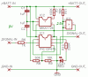
The MAX1726 is a 5V low dropout 20mA regulator.
R7 enables reverse battery protection in the MAX1726.
IC3 is a ZR431 2.5V shunt regulator (used as Vref).
R6 will current limit the input signal if this should be higher than the PIC's Vdd.
R8 and R9 is a voltage devider, to measure the battey voltage using the ZR431 as Vref for the internal AD converter ind the PIC.
The circuit will be powered by 4-5 NiMH cells.
Thanks for any suggestions 8)
Regards,
Futterama
I have been designing a circuit for a RC failsafe (puts throttle servo in brake position in a nitropowered RC car if there is radio-problems) and I want to hear your opinion on my component choice, resistor value choice ect.
Quick circuit explanation:
The MAX1726 is a 5V low dropout 20mA regulator.
R7 enables reverse battery protection in the MAX1726.
IC3 is a ZR431 2.5V shunt regulator (used as Vref).
R6 will current limit the input signal if this should be higher than the PIC's Vdd.
R8 and R9 is a voltage devider, to measure the battey voltage using the ZR431 as Vref for the internal AD converter ind the PIC.
The circuit will be powered by 4-5 NiMH cells.
Thanks for any suggestions 8)
Regards,
Futterama