Continue to Site

Welcome to our site!

Electro Tech is an online community (with over 170,000 members) who enjoy talking about and building electronic circuits, projects and gadgets. To participate you need to register. Registration is free. Click here to register now.

  • Welcome to our site! Electro Tech is an online community (with over 170,000 members) who enjoy talking about and building electronic circuits, projects and gadgets. To participate you need to register. Registration is free. Click here to register now.

Circuit of 195 Cig Mig welder

Status
Not open for further replies.

Gregory

Member
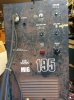
The welder is not feeding wirer and operating the circuit breaker .
I would like help to sort out the problem.
The circuit operates on 12 volt AC then is rectified to DC
I have arrived that there is 12 volts at 2 of the diodes and 16 volts at the other 2 Diods.
Why would there be 2 different voltages.
I need help to guid me through circuit .
I can take voltage readings on the board and post them.
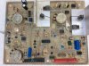
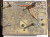
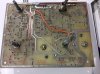
I do not have a circuit digram.
I have photoes of the circuit board. This may help you to guid me through the circuit
 

Attachments

  • IMG_2129.JPG
    IMG_2129.JPG
    1.5 MB · Views: 226
  • IMG_2133.JPG
    IMG_2133.JPG
    1.4 MB · Views: 220
  • IMG_2135.JPG
    IMG_2135.JPG
    768 KB · Views: 232
First guess is that a portion of the trace for this wire wound resistor:
upload_2017-10-16_8-17-12.png

appears to be missing some solder and, perhaps, even some of the PCB trace:
upload_2017-10-16_8-17-39.png

Over heating as well as some sparking might explain the damage. Not hard to imagine with a wire wound, higher current resistor that might be under sized (too low a wattage rating).
 
I have repaired the resistor track . The resistor measures .57 ohms using Esr meter, the value on the resistor indicates it looked like .8 of a ohm 10 W.
Having power on the board I have measured the voltage going to the board 12.4 v Ac at the 3 yellow pointes on the board in the photo. The trackes that are marked in red go to a SC141D Triac.
When I bridge out Mt1 to Mt2 or gate either one the main contact comes in.
The Blue marked points ar the hand piece switch engages the contact and the wirer feed motor to operate which are the red dots on the board.
Nothing is happening when I operate the welding gun even when I operate the hand piece There is no voltage on the red and blue points.there is Dc voltage on the 4 diods being the bridge rectifier. I am not sure where to go from here.
 

Attachments

  • IMG_2148.JPG
    IMG_2148.JPG
    1.4 MB · Views: 205
Last edited:
To be honest, Gregory, without a schematic all I can do is guess at the problem(s).

I suspect that the triac(s) are blown/open (since they are under the most severe load and the trace feeding them vaporized) but that is just a guess. Somewhat surprised the fuse didn't blow as well.

On that note, I've had many components sacrifice themselves to save a fuse... :banghead:.
 
On the circuit board the 2 blue dots is the switch that operates every thing but there is no voltage there and when bridged out nothing happening can you help me with this problem. Thank you
 
Is there any tests that you require on the board to help you to solv this problem.
Is there any members that may have a circuit digram of this welder.
 
Have you checked (or replaced) the fuse?

What is supposed to be the source of the voltage on the blue pins?
 
Status
Not open for further replies.

Latest threads

New Articles From Microcontroller Tips

Back
Top