Continue to Site

Welcome to our site!

Electro Tech is an online community (with over 170,000 members) who enjoy talking about and building electronic circuits, projects and gadgets. To participate you need to register. Registration is free. Click here to register now.

  • Welcome to our site! Electro Tech is an online community (with over 170,000 members) who enjoy talking about and building electronic circuits, projects and gadgets. To participate you need to register. Registration is free. Click here to register now.

Circuit Help

Status
Not open for further replies.

b_reagle

New Member
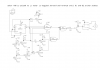
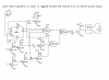
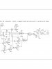
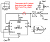
I am wanting to build an electric lock switchable by keychain remote. The remote and receiver will be from another company due to lack of knowledge on transmitters. All of the circuit will run on 4 AA batteries. I am wanting to know what bypass caps to put where and just a second opinion of my progress so far. Thanks for any help ahead of time!!View attachment 3 input doc.doc
 
Hi b_reagle,

Welcome to the forum. Just a couple of hints to help you get more responses in the future:

1) Try to use a descriptive subject line. "Circuit Help" really doesn't mean much; on a site like this, pretty much every thread is about "circuit help". ;)
2) Use image formats to post images. Document formats (like .doc) are for text/word processing. In this case, the image in the .doc doesn't fit on one page and it takes a little jiggery-pokery for others to be able to see it.

I've taken the liberty of extracting, rotating, resizing, and saving the image from the document file as a proper PNG image:
door_lock-png.21328


Anyway, enough babbling about that stuff. On to the actual question. :) I'd suggest starting with a 0.1uF across the power pins, located physically as close as possible to the pins, on both ICs. You may want another where the power enters the board as well, especially if the power supply leads are long.

For more information, you may find this document helpful:

If you add those caps and still have problems, post what results you're getting. And if I've missed some obvious spots I hope one of the more experienced members will step in and fill in the blanks.


Cheers,

Torben
 

Attachments

  • door_lock.png
    door_lock.png
    70.4 KB · Views: 228
It's always a good idea to add a 47 to 100µF electrolytic capacitor directly to the power supply pads. (voltage rating according to VDD) - besides the already suggested caps close to the supply pins of the ICs.

Boncuk
 
It's always a good idea to add a 47 to 100µF electrolytic capacitor directly to the power supply pads. (voltage rating according to VDD) - besides the already suggested caps close to the supply pins of the ICs.

Boncuk

Hans is absolutely right here: I forgot to mention the larger value for the main power supply bypass cap. It's good to know that it's always a good idea. I've always done it but that's just because I read somewhere to do it. Probably from Hans or another experienced member. :)


Torben
 
Thank you for the help. I also thank you for redrawing the circiut. I also needed to know what the value of R10 and R9 should be. The motor is rated for 800mA Max at 6 vdc. And if a 2n2222 would work if I put 2 in parallel( for the Q with no number at the end of the circuit). Also, is this a good way to do what I want done? Any help is greatly appreciated. Thanks again
 
Thank you for the help. I also thank you for redrawing the circiut. I also needed to know what the value of R10 and R9 should be. The motor is rated for 800mA Max at 6 vdc. And if a 2n2222 would work if I put 2 in parallel( for the Q with no number at the end of the circuit). Also, is this a good way to do what I want done? Any help is greatly appreciated. Thanks again

Hi B,

I have a couple of questions for you.

First: Does RLY1 represent the coil of a relay, with the switch on the motor representing the switching portion of the same relay?

Second: The way the switch on the motor is drawn, I don't see how it can possibly work. Motors aren't something I have a lot of experience with but it sure looks like no matter which way the switch goes, the two sides of the motor will just be shorted together.

Third: did you design the circuit? I only ask because it seems a little complex for what I think you are trying to achieve.

Fourth: can you explain (in as much detail as you can) exactly what you are trying to accomplish here? So far I know that it's supposed to go one way and then the other, but I want to know how you intend to connect this thing to the remote receiver and what the specs of the receiver itself are.

I don't see any immediate reason that you couldn't parallel two 2N2222s to replace the unmarked transistor. I'm going to leave the question of the resistor values alone until you've answered the questions above, if that's OK. :)


Cheers,

Torben
 
Question 1.. Yes. It is the same 5vdc DPDT relay.
Question 2.. Sorry, Schematic is wrong. I have put in a new one.
Question 3.. Yes
I am going to try to fit the circuit in my dead bolt on my front door. The circuit will toggle(pin 1 on U1 =1) the motor forward until Q1 and Q2 are both on(1). Then pulse J1 to toggle the relay and circuit(pin 1 on u1 =0). The motor is reversed and on until Q1 and Q2 are off(0). As for the reciever and keychain transmitter, I will have to buy aftermarket items. Maybe X10. Their reciever is should be easy to hook into. I was going to hook this to a tone transmitter. Then I could have several locks operate at once. I have used tone decoders before so I have some experience with them. Not quite on this scale though.
 

Attachments

  • 3 input door png.png
    3 input door png.png
    67.8 KB · Views: 119
I am just trying to make electric door lock with keychain remote. And for all of it to be as small and as efficient as possible. Thank you again Torben and Boncuk for your help.
 
The base current of two 2N2222 transistors is 40ma each when their load current is 400mA each. Then their max saturation voltage loss is 2.5V so the 5V motor will barely run.

But the minimum output current from the CD4023 is only 1mA and 80mA is needed.

Instead of two 2N2222 transistors use a logic-level Mosfet like an IRF3711ZL that will have an extremely low voltage loss.
 
Should I use mosfets for all the transistors? I want the circuit to be small an efficient. The output max current is 800mA not 80mA, as I think you were refering to, or am I misunderstanding? This may change to a higher number. I am not sure if the motor is powerful enough to spin the lock. I should be able to fix that with gearing.
 
I have a working prototype on breadboard, but it is using 2 input nand gates(CD4011BE) for the logic along with a CD4013BE for the flip flop. The motor does switch forward and reverse, and when I shine a flash light on the phototransistors it shuts off the way it should. I do not have a load on the motor. I only had these chips. Now I want to make it smaller. With 3 input nand chips that elimanates one chip. Now I am down to two. Thanks for the input..
 
Last edited:
The output transistor has a load current of 800mA which is too high for a single 2N2222. So if two 2N2222 transistors are in parallel then their load current is 400mA each. If each one has a base current of 40ma then the max saturation voltage loss is 2.5V.

The Cmos IC cannot supply anywhere near 80mA to drive the bases of two 2N2222 transistors and the transistors have too much voltage loss anyway.

The other transistors in your circuit have very low currents and don't need to be replaced with Mosfets.
 
What would the values of R9 and R10 be with mosfets?
 
What would the values of R9 and R10 be with mosfets?
100 ohms is fine for R9.
R10 is not needed but should be a diode to arrest the high voltage developed by the inductance of the motor when it is turned off.
 

Attachments

  • Mosfet driving motor.PNG
    Mosfet driving motor.PNG
    9.7 KB · Views: 108
Nevermind the flip flop... mosfet it is. Just R9 and if I even need R10
 
Here is the new schematic. Is R11 a good value or should it be lower. I do not know the current for the relay. Is this how you would make this circuit. Thank you for the help audioguru.
 

Attachments

  • doorswitch2.jpg
    doorswitch2.jpg
    155 KB · Views: 143
The value of R11 might be so low that it drags down the logic voltage then it will never be a logic high.
You must find out the current of the relay to calculate a suitable value for R11.

You are using ordinary Cmos that has a very low minimum output current of only 1mA when its supply is only 5V. The output current is 7mA if the supply is 10V and is 10mA if the supply is 15V.

74HCxx high speed Cmos has an output current of 25mA when its supply is 5V. It would work fine in your circuit.

A 5V relay draws a lot of current. Then the driver transistor needs to have a lot of base current. The 2.2k value for R11 causes a current of about 1.5mA which is too much current for a weak but passing Cmos gate. The 2.2k base resistor allows the 2N2222 transistor to drive a relay that uses about only 30mA.
A higher voltage relay draws less current and the Cmos gates can supply plenty of current.
 

Attachments

  • motor control.PNG
    motor control.PNG
    41.5 KB · Views: 115
I was trying to make this battery operated.(4 AA batteries) Which would give me almost 6 volts. Would the 74hc series need regulated 5 volts?
 
Status
Not open for further replies.

New Articles From Microcontroller Tips

Back
Top