Continue to Site

Welcome to our site!

Electro Tech is an online community (with over 170,000 members) who enjoy talking about and building electronic circuits, projects and gadgets. To participate you need to register. Registration is free. Click here to register now.

  • Welcome to our site! Electro Tech is an online community (with over 170,000 members) who enjoy talking about and building electronic circuits, projects and gadgets. To participate you need to register. Registration is free. Click here to register now.

circuit for pwm fan control

Status
Not open for further replies.

spirosd

New Member
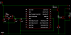
I would like some help in putting together a circuit for controlling fans through pwm. Does the attached circuit makes sense? I have added the npn amplifier and mosfet as the pic (16f628a) is not capable of driving the fans (2x12V) directly. I should probably also isolate the CCP1 pin using an optocoupler.

This is first itteration, once this is working, the next step would be to add temperature sensing (Dallas DS18B20). For those interested, the aim is to produce an "automagical" way of controlling fans used to cool the primary mirror of a newtonian telescope.

Thanks for your help
 

Attachments

  • pwm_circuit.png
    pwm_circuit.png
    10.9 KB · Views: 1,021
What's T1 for?.

The fans that I need to power are 12V. I assume that Q1 needs to be driven at 12V. The CCP1 output from the pic would be 5V so, use T1 to amplify to the 12V.
 
spirosd said:
What's T1 for?.

The fans that I need to power are 12V. I assume that Q1 needs to be driven at 12V. The CCP1 output from the pic would be 5V so, use T1 to amplify to the 12V.

T1 is an emitter follower, so will only drive the gate of Q1 to about 4.3V - LESS than the PIC on it's own will do!. The gate voltage isn't dependent on the drain supply, but on the switching characteristics of the FET - many FET's are logic level, and will work fine straight from the PIC. But in any case, as it's wired T1 is only making things WORSE.
 
Nigel Goodwin said:
spirosd said:
What's T1 for?.

The fans that I need to power are 12V. I assume that Q1 needs to be driven at 12V. The CCP1 output from the pic would be 5V so, use T1 to amplify to the 12V.

T1 is an emitter follower, so will only drive the gate of Q1 to about 4.3V - LESS than the PIC on it's own will do!. The gate voltage isn't dependent on the drain supply, but on the switching characteristics of the FET - many FET's are logic level, and will work fine straight from the PIC. But in any case, as it's wired T1 is only making things WORSE.

I take it from your reply that I can remove T1 and drive Q1 directly from the pic.

I should be able to utilise the pwm output to control the voltage to
> peltier device
> step motors (in place of a chopper circuit)

Greatly appreciate your input Nigel.
 
spirosd said:
I take it from your reply that I can remove T1 and drive Q1 directly from the pic.

Yes, no matter what the FET it will be better than with it, but with a logic level FET it will switch fully (I'm not sure if that FET is logic level or not?, the datasheet should tell you).
 
Nigel Goodwin said:
Yes, no matter what the FET it will be better than with it, but with a logic level FET it will switch fully (I'm not sure if that FET is logic level or not?, the datasheet should tell you).

Looking at the datasheet for the irf510 from intersil it says
... These types can be opearated directly from integrated circuits. ....
I think it's time to try the circuit.

Thank you for your help.
 
Nigel Goodwin said:
spirosd said:
I take it from your reply that I can remove T1 and drive Q1 directly from the pic.

Yes, no matter what the FET it will be better than with it, but with a logic level FET it will switch fully (I'm not sure if that FET is logic level or not?, the datasheet should tell you).

I suggest that you connect a 100 Ohm resistor between the PIC output and the gate of Q1. As I understand it, this prevents the possibility of spurious oscillation.
 
ljcox said:
I suggest that you connect a 100 ohm resistor between the PIC output and the gate of Q1. As I understand it, this prevents the possibility of spurious oscillation.

Would that be in place of the 1K resistor or, in addition to?
 
Thank you Len,

I am attaching the modified circuit.

Thanks again to you and Nigel for your help.
 

Attachments

  • pwm_circuit_128.png
    pwm_circuit_128.png
    10.5 KB · Views: 927
You don't need to use 7805 for the PIC. A 78L05 the size of a TO-92 transistor is suffice and it don't need a heatsink.

The value of capacitors(C1 & C2) at the input and output of the regulator is a bit low consider that you are driving a DC motor. You'll get better reliability against motor noise by using 100uF or higher for C1 and 10uF for C2.

I would also add a 100K resistor from the gate of IRF510 to Vss as the PIC would reset to open circuit(high impedance) regarding its port pins.
 
I dunno about the 100 ohm inline with the gate ... I guess it can't hurt, since the gate only requires microamps to switch off to on

however, I would recommend a pulldown between the gate and ground (easy way is your source pin is ground, just connect a 10k resistor between pins 1 and 3 on the fet)

the pull down prevents the mosfet from entering linear or resistive mode should something happen to the control signal from the pic (for example PIC browns out or resets or locks up or whatever)

without a pulldown to ground, the gate could be left floating, meaning the mosfet would be partily conducting, and incur massive power dissipation. this way, the pulldown forces the switch off unless the pic specificly tells it to be on

also, check the datasheet for your mosfet ... most of the IRF5xx are in the International Rectifier HEXFet series, and have internal clamping diodes, eliminating the need for D1... in fact, page two of the IRF510 datasheet clearly describes the internal protection diode

last thing... the RdsON of that fet is pretty poor, compared to what's available now ... that device is not what I'd call a "logic level" mosfet ... depending on the load being switched, it might not make a difference... but if you're trying to pwm some monster fan you probably won't see full voltage at the fan, since the 5v from your PIC won't be enough to fully switch the mosfet. this also means your mosfet will be getting pretty warm, since it's in resistive mode and not switching the full current.
 
justDIY said:
also, check the datasheet for your mosfet ... most of the IRF5xx are in the International Rectifier HEXFet series, and have internal clamping diodes, eliminating the need for D1... in fact, page two of the IRF510 datasheet clearly describes the internal protection diode.

The diode in the datasheet is the intrinsic body diode. The diode in the OP's circuit is there to prevent back emf of the load affect other part of the circuit. They serve different functions and is not one or the other. One still needs the D1 diode even using a MOSFET with an intrinsic diode.
 
justDIY said:
I dunno about the 100 ohm inline with the gate ... I guess it can't hurt, since the gate only requires microamps to switch off to on

I can't recall where I read this, but they said some FETs will oscillate without it.

however, I would recommend a pulldown between the gate and ground (easy way is your source pin is ground, just connect a 10k resistor between pins 1 and 3 on the fet)

Agreed. If you are confused by the difference between eblc's recommendation of 100k and this one, don't worry. Anything between 10 k and 10 M would suffice.
 
justDIY said:
last thing... the RdsON of that fet is pretty poor, compared to what's available now ... that device is not what I'd call a "logic level" mosfet ... depending on the load being switched, it might not make a difference... but if you're trying to pwm some monster fan you probably won't see full voltage at the fan, since the 5v from your PIC won't be enough to fully switch the mosfet. this also means your mosfet will be getting pretty warm, since it's in resistive mode and not switching the full current.

Thank you for your help. The mosfet that is being used is what I have currently in 'the box'. I was also concerned about the voltage from the pic switching the fet, hence my initial addition of an 2N2222 to ensure sufficent voltage at the gate. Perhaps I should add that back on?

eblc1388 said:
The value of capacitors(C1 & C2) at the input and output of the regulator is a bit low consider that you are driving a DC motor. You'll get better reliability against motor noise by using 100uF or higher for C1 and 10uF for C2.

I would also add a 100K resistor from the gate of IRF510 to Vss as the PIC would reset to open circuit(high impedance) regarding its port pins.
Thank you (and Len) for your advice. Will be adding these.
 
spirosd said:
I was also concerned about the voltage from the pic switching the fet, hence my initial addition of an 2N2222 to ensure sufficent voltage at the gate. Perhaps I should add that back on?

Don't do it like it was!, as I said before, you had connected the transistor so as to DECREASE the voltage available to the gate (0.7V less than the PIC on it's own will provide).
 
Nigel Goodwin said:
Don't do it like it was!, as I said before, you had connected the transistor so as to DECREASE the voltage available to the gate (0.7V less than the PIC on it's own will provide).

I misread your previous comment, if it seemed to be implying error on your part I apologise. Thank you for clarifying.

I am attaching a revised schematic.

Thank you very much for the input from you all. Your help is greatly appreciated.
 

Attachments

  • pwm_circuit_694.png
    pwm_circuit_694.png
    11.3 KB · Views: 567
That won't work either! - the transistor will be permanently ON - to turn T1 OFF the base needs to rise to 12V, the PIC pin only goes as high as 5V, so it will never get close to turning OFF. The 100 ohm resistor will also probably destroy the PIC (and perhaps T1?), as it passes 120mA through it's base emitter junction, through the PIC I/O pin to ground.

Check my PIC tutorial 'Hardware Extras' section for how to source a higher voltage from a PIC pin - the actual example shows it feeding a lamp.
 
Status
Not open for further replies.

New Articles From Microcontroller Tips

Back
Top