Almost there!
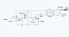
1- If you have addwd any resistors in series with the input signal remove them. I put one in the drawing to represent the protection that may be in the computer.
2- Change the input capacitor to 10 Ufd. This is needed because the input frequency is kind of low.
3- Change C2 to 10Ufd. and move it to the collector of the transistor to ground.