Continue to Site

Welcome to our site!

Electro Tech is an online community (with over 170,000 members) who enjoy talking about and building electronic circuits, projects and gadgets. To participate you need to register. Registration is free. Click here to register now.

  • Welcome to our site! Electro Tech is an online community (with over 170,000 members) who enjoy talking about and building electronic circuits, projects and gadgets. To participate you need to register. Registration is free. Click here to register now.

Circuit equivalence clarification

Status
Not open for further replies.

croese

New Member
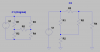
I'm still fairly new at electronics and I tend to do a lot of rearranging of circuit diagrams to make them easier to read. I came across a diagram that had 2 parallel branches with a resistor bridging them (C1 in the attached file). I rearranged it into (what I think) is the equivalent circuit C2, but in a layout that's easier for me to tell what things are actually in series or parallel with others. C3 is a conversion of C1, but I replaced the lower group of resistors in a delta form into a Y form (this is why labels are RT# since they're different values).

What I was wondering is if someone could tell me if I rearranged C2 and C3 correctly and give me any pointers if I didn't.
 

Attachments

  • equiv_question.pdf
    9 KB · Views: 159
The two circuits are not the same. The original is a wheatstone bridge circuit and is in the standard schematic form for such circuits.

To be equivalent all resistor junctions must go to their original locations. For example, in the C2 schematic, R3 and R5 are in series with no other connection between them. The original circuit has R4 connected to the junction of R3 and R5. If you remove R4 from the connection to R2 and, instead, connect it to the junction or R3 and R5, then the two circuits will be equivalent.
 
equiv circuits

The two circuits are not the same. The original is a wheatstone bridge circuit and is in the standard schematic form for such circuits.

To be equivalent all resistor junctions must go to their original locations. For example, in the C2 schematic, R3 and R5 are in series with no other connection between them. The original circuit has R4 connected to the junction of R3 and R5. If you remove R4 from the connection to R2 and, instead, connect it to the junction or R3 and R5, then the two circuits will be equivalent.

Yes, in C2 you do not have a common point which connects R3, R4 and R5.:confused:
 
Ok, thanks for pointing that out you two. I think I have it now (see attached). I've included the ground in this schematic because I still have trouble with a couple things here:

1) It's clear from the new drawing that the branch with R4 is in parallel with everything else, but what about R2? Is it shared between the 2 branches? (branch 1 being R1 -> R2 -> Ground and branch 2 being R3 -> R5 -> R2 -> Ground)

2) How do the resistors combine in this case? Is it something like R4 || ((some combination of R1, R3, and R5) + R2)?

Basically the reason I've been trying to rearrange this thing is that when it's in the bridge form, I have trouble telling which resistors are in parallel or series with the others and so have trouble with calculating certain things like total resistance (see #2 above). Is there any other way I can push these things around to make it look more "conventional?"
 

Attachments

  • try_again.png
    try_again.png
    26.8 KB · Views: 147
Basically the reason I've been trying to rearrange this thing is that when it's in the bridge form, I have trouble telling which resistors are in parallel or series with the others and so have trouble with calculating certain things like total resistance (see #2 above). Is there any other way I can push these things around to make it look more "conventional?"

This is the classic Wheatstone bridge topology, and you can't simplify it by just looking for ways to reduce various series and parallel combinations. You have to use the Y-Delta transformation:

Y-Δ transform - Wikipedia, the free encyclopedia

For example, R2, R4 and R5 form a delta; transform them into a Y and you can then use simple parallel and series combinations to finish the analysis.
 
I figured that was probably the case (I did the transform in the schematic in the original post -- C3), but thanks for confirming that.
 
Status
Not open for further replies.

New Articles From Microcontroller Tips

Back
Top