Gregory
Member
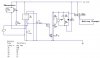
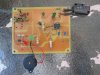
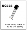
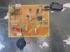
Having desigined the Posted Circuit I powered the circuit up and smoke came out of the Transistor and 555.
The circuit is temperature driven design which trippes the 12V Dc 40A relay which then gives off a audible and visual Alarm (red led)
Is there something wrong with the circuit.
The circuit is temperature driven design which trippes the 12V Dc 40A relay which then gives off a audible and visual Alarm (red led)
Is there something wrong with the circuit.