Electro Tech is an online community (with over 170,000 members) who enjoy talking about and building electronic circuits, projects and gadgets. To participate you need to register. Registration is free. Click here to register now.
Welcome to our site! Electro Tech is an online community (with over 170,000 members) who enjoy talking about and building electronic circuits, projects and gadgets. To participate you need to register. Registration is free. Click here to register now.
Please my project reqiures the use of rain sensor to vary the resistance of a resistor in acordance with the intensity of the rain.I need the circuit diagram of the sensor, indicating the correct values of the components required.
I just saw a rain detector circuit at https://www.aaroncake.net/circuits/lie.htm
. It was posted in another section of this site. Click on the bottom of the page where it says to return to main page. Scroll down the list of topics and you wll find the rain detector.
In what units is "intensity of rain" measured? What physics is involved in measuring rain intensity? Can you define the requirements for such a sensor?
I'm trying very hard to understand this but I'm drawing a blank.
..measuring the amount of water collected in an unit time(say 1 min) would give an idea about the 'intensity' of rain..but as u see ..it's far from real time..
So your suggestion is to measure volume per unit time in units such as milliliters per minute. OK so we need a way to measure liquid volume, and we need a way to flush the measurement volume so we can repeat the measurement in the next time interval.
I would suggest that it might be easier to measure weight. Since we know the density of water we can compute the volume. Flushing the container then becomes more of a problem.
Rain is generally measured in depth, so you could say "we had three inches of rain last week".
Obviously all you need to do this is a container, and measure the depth of rain that collects in it. However, this is rather insensitive, so you would usually pour the water into a narrow measuring jug, which gives much greater resolution on the scale - obviously there's a conversion factor involved. Next 'improvement' is to collect the water in a funnel (for the large collecting area), and have the funnel feed directly into the measuring jug.
This is still manual though, and you have to empty the jug as well.
An electronic method is to use a 'see-saw' that works a switch (usually a reed, so there's no mechanical force required). The 'see-saw' accepts water from the funnel on one side, once it gets too heavy the see-saw changes over, the water is tipped out, and the funnel feeds the second side, until that gets too heavy, and so on. This gives a pulse from the reed relay, the speed of which is dependent on the level of rain fall.
You can count the number of pulses for a long term measure of the rainfall, or you can measure the time between them for a fairly real time measure of the amount of rain falling. Obviously it depends on how big the see-saw is, and how much water it requires to tip over.
EDIT: WELL!! - while I was typing someone posted a picture!!
I was reading through his project notes (so easy to get sidetracked here) on the rain tipper **broken link removed** from an earlier post here.
Some obsevations
Digital inputs are configured for use with dry contact switches. They are not opto-isolated. They are very hard to destroy however and will probably withstand even accidental connection of either terminal to 110VAC without damage.
I have not tried it though. They all have schmitt inputs with RC debounce built in.
The larger the funnel opening the more sensitive it is, so you can make it as big as you like - calibrate it by pouring a known amount of water down the funnel (slowly!).
The larger the funnel opening the more sensitive it is, so you can make it as big as you like - calibrate it by pouring a known amount of water down the funnel (slowly!).
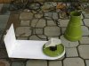
Example if you collected rain with a funnel you would collect scads of it compared to a smaller opening. The tipper in the picture has a tapered opening smaller at the top than the base.
I'm sure you could calculate an equation?, you need to know the accurate level the tipper tips at, and the surface area of the funnel opening - just basic maths!.
Example if you collected rain with a funnel you would collect scads of it compared to a smaller opening. The tipper in the picture has a tapered opening smaller at the top than the base.
No it doesn't, it's not clear from the picture, but the top part is a funnel, with the narrow end at the centre of the 'tipper', the part that goes wider at the bottom is just a housing (it's wider to clear the tipper).
They built one in a VERY old issue of Practical Electronics (now EPE), apparently the biggest problem is surface tension stopping the water tipping out correctly - but presumably the plastic tipper shown is probably better?, the Pratical Electonics article used a metal tipper soldered together.
BTW, the article fed a mechanical counter, it was probably pre-logic IC's!.
So your suggestion is to measure volume per unit time in units such as milliliters per minute. OK so we need a way to measure liquid volume, and we need a way to flush the measurement volume so we can repeat the measurement in the next time interval.
I would suggest that it might be easier to measure weight. Since we know the density of water we can compute the volume. Flushing the container then becomes more of a problem.
Can somebody help me with a schematics and functional description for a rain sensor for automotive. I would like to use a LED and a photodiode for the sensor.
I don't know how to connect this with the wipers or to any drive unit (?!).
Do you have any ideas about a complete schematic including the sensor and the driver for wipers?
At Dollar Tree stores (in USA) they sell pedometers for $ 1.00. These could easily hacked for a neat five (5) digit totalizator for a project like this.
It will also make a great counter for a coil winder.
Picture: $ 1.00 Pedometer photo - Rolf photos at pbase.com **broken link removed**
Can somebody help me with a schematics and functional description for a rain sensor for automotive. I would like to use a LED and a photodiode for the sensor.
When I saw the original post this is the application I thought he was asking about.
Since he asked about having a variable resistance in proportion to rain intensity, I don't see how using a tipper or other water collection device would work. I think he wants something that's "real time" that gives instant feedback based on how hard it's raining - probably for an automatic wiper function.
The ones I've read about seem to rely either on capacitance in an area of the windshield or on reflected light.
This site uses cookies to help personalise content, tailor your experience and to keep you logged in if you register.
By continuing to use this site, you are consenting to our use of cookies.

")