Continue to Site

Welcome to our site!

Electro Tech is an online community (with over 170,000 members) who enjoy talking about and building electronic circuits, projects and gadgets. To participate you need to register. Registration is free. Click here to register now.

  • Welcome to our site! Electro Tech is an online community (with over 170,000 members) who enjoy talking about and building electronic circuits, projects and gadgets. To participate you need to register. Registration is free. Click here to register now.

Circuit Board Design Tips

For The Popcorn

Well-Known Member
Most Helpful Member
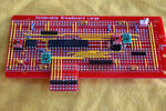
The picture shows the vending machine control board I'm just finishing up. You may notice an abundance of 0.1" pitch KK type headers i have a couple tips to help get 0.1" pitch headers nicely installed.

20250502_140154.jpg


The first tip is to use "lock" pcb footprints developed by Spark Fun. Alternate holes are positioned slightly above or below the baseline. This offset ensures the connector is perpendicular to the board. Details and links to the Spark Fun are at this link.

Jon's Imaginarium Lock Footprints

The second tip is to space header connectors on a grid according to the pitch of the headers, leaving an empty position between connectors. This leave room for the mating connectors. In the context of this discussion, it allows you to bridge all of the connectors with a female header strip, aligning the connectors. Add a couple of spring clamps and the connectors are held in position while you get them soldered in place.


20250502_124536.jpg
 
The first tip is to use "lock" pcb footprints developed by Spark Fun. Alternate holes are positioned slightly above or below the baseline. This offset ensures the connector is perpendicular to the board. Details and links to the Spark Fun are at this link.
Pretty useful, thanks for sharing this
 
The first tip is to use "lock" pcb footprints developed by Spark Fun. Alternate holes are positioned slightly above or below the baseline. This offset ensures the connector is perpendicular to the board. Details and links to the Spark Fun are at this link.
That might solve one problem, but it creates others. Forcing a pin to be pushed against the wall of a plated-through hole during soldering is not a god idea.

First, it creates a void in the solder where the only thing assuring contact between the pin and copper is friction. This is fine for press-fit connectors designed for this, but for "normal" parts it is not a "gas-tight" connection.

Second, it makes the connector very difficult to remove when using a vacuum desoldering station.

A better way to assure that the pins are nicely aligned across the row is to use your second tip: Using the strip socket as a carrier, load all of the connectors into the socket, then install the entire row on the board as a single component, solder everything, and remove the strip socket.

ak
 
The only "problem" I have observed using lock footprints is finding out some months after soldering a board together was when I was unpluging a connector and the header came off the circuit board – I had missed soldering it, and it was working well despite that omission. This "problem" can be handy for making temporary connections like an ICSP header. Insert a header during dev, then remove it when you're finished.

I have to question your "gas tight" point as well. These headers have square pins, just like wire-wrap headers and sockets. The very slight interference fit created by a lock footprint causes the header pins to slightly score into the hole plating.... if you believe claims about wire-wrapping, the sharp corners of the pins bite into the wire, creating a gas tight connection. Hmmm. A lot of complex (i.e., hundreds if not thousands of connections) of gear with wire-wrap connections is still going strong, so maybe they knew what they were talking about.

The Sparkfun article documents the efforts made to determine and test the optimal spacing. It was pretty well researched, and Sparkfun has been using it for years.

I'm not here to debate the idea. I have found it useful without any problems. Please feel free to use it or not as you see fit.

Of course, one has to wonder how many headers you unsolder that this would be a major concern......
 

Latest threads

Back
Top