Continue to Site

Welcome to our site!

Electro Tech is an online community (with over 170,000 members) who enjoy talking about and building electronic circuits, projects and gadgets. To participate you need to register. Registration is free. Click here to register now.

  • Welcome to our site! Electro Tech is an online community (with over 170,000 members) who enjoy talking about and building electronic circuits, projects and gadgets. To participate you need to register. Registration is free. Click here to register now.

circuit analysis_2

Status
Not open for further replies.

Adam2014

Member
Hi
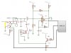
already , i have been asked for the attachment circuit but i don't have enough answers.
Q1) for the integrator R2,C7 its output is a triangular wave or still constant and why? why we use the shown value ?
Q2) the output is between Vcc/3 and 2*Vcc/3 or between 0 and 5 ?
 

Attachments

  • lc.jpg
    lc.jpg
    159.6 KB · Views: 154
Q1) for the integrator R2,C7 its output is a triangular wave or still constant and why? why we use the shown value ?
Do you mean R2/C4? It depends. If an LC resonant circuit is connected to the left of C3, then the voltage on C4 will become somewhat stable (should be around half the supply voltage, I guess). If no LC circuit is connected, then the voltage on C4 will charge and discharge between Vcc/3 and 2Vcc/3 at some arbitrary frequency (not critical for this circuit to operate in the application it's designed for).

The output is between ~0 and the supply voltage (Which I've referred to as Vcc above).
 
Status
Not open for further replies.

Latest threads

New Articles From Microcontroller Tips

Back
Top