Electro Tech is an online community (with over 170,000 members) who enjoy talking about and building electronic circuits, projects and gadgets. To participate you need to register. Registration is free. Click here to register now.
Welcome to our site! Electro Tech is an online community (with over 170,000 members) who enjoy talking about and building electronic circuits, projects and gadgets. To participate you need to register. Registration is free. Click here to register now.
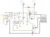
Your schematic is too fuzzy to read the details.
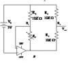
The opamp has a dual polarity supply but the inputs and output of the opamp have no 0V (ground) reference voltage so it probably will not work.
The junction of the positive and negative supplies will be 0V and is the input reference (for the positive terminal of the 5V battery) and the 0V junction of the supplies is also the output reference voltage.
Your new opamp circuit with the LF411 opamp is an attenuator, not an amplifier. Its output is -0.5V.
I do not know why you have R2 mixing some of the inverted output with the input through R1.
sorry it's an old image
i change LF411 to TL074 later
Vout is negative thus i can't measure it using MCU
so i measure the positive voltage V1 then calculate R3 (unknown resistor)
so i need its analysis and how its work exactly , please !
i use more than one reference resistance R4 and i switch between them using a rotary switch
and its value equal maximum value can the meter measure because Rx= -Vout/Vcc * R4
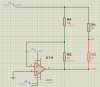
The circuit is just an amplifier with a fixed input. When you change R3 you change the gain and thus you change the output voltage changes.
Since the input is 5v and the resistor R4 is 10k and it's an inverting amplifier that means we have:
Vout=-5*R3/R4
so when you change R3 you'll see Vout change accordingly. You can then calculate R3 with:
R3=-Vout*R4/5
But basically it is just an inverting op amp amplifier so you can follow the theory for that to understand how it works better. Usually people just follow the gain formula as above where the gain is -R3/R4.
This all assumes that your op amp can work with plus and minus 5v or else you change the power supplies.
BTW R1 and R2 really are not needed if you use a regular op amp.
thanks Mr Al
* i use R1 , R2 because Vout is negative thus i can't measure it using MCU thus i use R1 , R2 to have a voltage divider V1
then i measure V1 using ADC (MCU) then i calculate Vout while(Vout = 2V1 - Vcc) .
you have an idea about a (max,min) measure range if i replace R4 by a variable resistor
i use more than one reference resistance R4 and i switch between them using a rotary switch
and its value equal maximum value can the meter measure because Rx= -Vout/Vcc * R4
That equation is good for the new circuit. Notice that R1 and R2 do nothing but load the op amp down.
The op amp will adjust the output voltage so that the voltage at junction of R3 and R4 is always zero volts, but the output voltage of the op amp cannot go below the power supply voltage of -5V in the real world (even though it might in the simulation world). That means that for Rx greater than R4 the output will not hold to the equation.
thanks Mr Al
* i use R1 , R2 because Vout is negative thus i can't measure it using MCU thus i use R1 , R2 to have a voltage divider V1
then i measure V1 using ADC (MCU) then i calculate Vout while(Vout = 2V1 - Vcc) .
you have an idea about a (max,min) measure range if i replace R4 by a variable resistor
Ok that makes prefect sense now. However, as ccurtis mentioned you do still have a limitation on what value R3 can take on. With R3=R4 that's the upper end of the range, as R3 can not go higher because of:
Vout=-5*R3/R4
would result in Vout going more negative than -5v and that can not be done nor do you want that to happen anyway because then V1 would go negative and you dont want that either.
So the upper limit on R3 is R3<=R4, and actually with a real op amp R3 has to be just a little less than R4 so we have R3<R4. The lower limit looks like zero because zero for R3 would make it a buffer with an output of zero. Thus the entire range of Vout is -5v to 0v, and unfortunately that means the output at V1 is only 0v to 2.5v which is too limited i believe and a better circuit could be constructed that takes advantage of the full 0 to 5v range of the ADC (assuming that's what you have, but if you have a 3.3v ADC then that's a different story but it could still be improved).
A simple improvement would be to add another op amp stage that converts 0 to 2.5v to 0 to 5v.
The limit on R4 should probably be around 1k to 100k. There's a chance it can work up to 1 meg if there isnt too much noise.
You might also look at any errors that can develop due to the input offset voltage too. The gain is limited so that's at least a plus factor.
another circuit i want to understand it very well (attached image)
Q1) for the integrator R2,C7 its output is a triangular wave ? why we use the shown value ?
This site uses cookies to help personalise content, tailor your experience and to keep you logged in if you register.
By continuing to use this site, you are consenting to our use of cookies.

")