Continue to Site

Welcome to our site!

Electro Tech is an online community (with over 170,000 members) who enjoy talking about and building electronic circuits, projects and gadgets. To participate you need to register. Registration is free. Click here to register now.

  • Welcome to our site! Electro Tech is an online community (with over 170,000 members) who enjoy talking about and building electronic circuits, projects and gadgets. To participate you need to register. Registration is free. Click here to register now.

Circuit advise

Status
Not open for further replies.

Burnt

New Member
Hi,

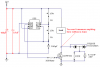
I have built what seemed to be a simple 555 timer circuit with variable resistors to adjust the output frequency of the 555 timer.
There seems to be some issues with the circuit when viewed on my PC based O/Scope & i would like to ask for some advise regarding these issues as i am inexperienced in electronics.
I have attached the Schematic of the circuit.

All tests done with 12V input:

First up, i noticed there is a "dip or voltage drop" --(not knowing the correct electronics term) in the signal along the peak voltage lines so the peak signal is not clean.
Attached as "Voltage Drop"

The second issue is the voltage output is not stable & seems erratic, i am not sure if it is characteristic of this particular circuit or i have some problems?

The output voltage will stay stable for a few seconds & then becomes erratic & starts jumping around in small increments & keeps increasing until it jumps from around 5v to just over 20v for a few seconds & then goes stable again & so on.
I noticed that the output frequency also changes when it jumps to the lower voltage marks as can be seen in the attachment.
In the Attachment --Erratic Voltage--i have captured the changes in the output voltage--Again with a constant 12v input.

I have another attachment--Frequency-- that shows the Minimum to Maximum Frequency of the Circuit. The higher frequency is not clean, i would like to get a nice clean signal.

Seems i have a few issues & i am not sure if it is the particular circuit design or not?

Any help would be greatly appreciated.
 

Attachments

  • Schematic.gif
    Schematic.gif
    45.2 KB · Views: 229
  • Voltage Drop.gif
    Voltage Drop.gif
    5.4 KB · Views: 141
  • Erratic Voltage.gif
    Erratic Voltage.gif
    5.4 KB · Views: 141
  • Frequency.gif
    Frequency.gif
    6.6 KB · Views: 147
Last edited:
1) Get rid of the 1N4007 diode and 100 ohm resistor. Pin 1 is supposed to be grounded.
2) Add a 100uF electrolytic and 0.1uf ceramic disc capacitors from +12V to ground.

What is a "peak voltage line"? The +12v is supposed to be a steady +12V.
The 1N4749 is a 24V zener diode so it won't do anything with a 12V supply.
Where in the circuit did you measure the voltage drop?
When the output of the 555 is high then it is at +10.7V.

Where in the circuit did you measure the red trace for erratic voltage?
Where in the circuit did you measure the green trace for erratic voltage?

The frequency traces look very steady. Where in the circuit did you measure them?
 
Thanks audioguru,
-----------
"2) Add a 100uF electrolytic and 0.1uf ceramic disc capacitors from +12V to ground."
-------------

You will have to excuse my ignorance with electronics & terms etc?
Where on the circuit do i add these?

-------------
"What is a "peak voltage line"? The +12v is supposed to be a steady +12V."
---------

I was reffering to the dip on the top of the trace pattern & marked this as voltage drop?

------------
"Where in the circuit did you measure the voltage drop?
Where in the circuit did you measure the red trace for erratic voltage?
Where in the circuit did you measure the green trace for erratic voltage?
The frequency traces look very steady. Where in the circuit did you measure them?"
----------
All the measurements were done at the output terminals to the coils--no coils connected at this stage so no load. I thought this was best until i sort it further.

Hope i have answered correctly
Thanks
 
All the measurements were done at the output terminals to the coils--no coils connected at this stage so no load.
With no load then the drain of the Mosfet does nothing. Your 'scope is picking up signals from outer space.

"From +12V to ground" should be very clear about where to connect the important capacitors.

Why did you have a 24V zener diode at the +12V connection?
 

Attachments

  • coil driver.PNG
    coil driver.PNG
    46.8 KB · Views: 144
With no load then the drain of the Mosfet does nothing. Your 'scope is picking up signals from outer space.

"From +12V to ground" should be very clear about where to connect the important capacitors.

Why did you have a 24V zener diode at the +12V connection?


Thanks again audioguru, your replies are very helpful.

Hahaha, i get what your saying with no load.

"From +12V to ground," I just wanted to make sure where they needed to go,

The 24v Zener diode was to suppress any spikebacks from the coil protecting the 555 timer?.
Is this the wrong idea?
I am very new to electronics & may very well have the wrong idea's about a lot of things?

I will make the changes you suggest when i have the components & then test with a load. I will also need a larger heatsink on the Mosfet before i load the circuit.
 
The 24v Zener diode was to suppress any spikebacks from the coil protecting the 555 timer?.
Is this the wrong idea?
The power supply is supposed to be strong and well filtered. The absolute max supply voltage for a 555 is only 18V anyway.

The coil makes a voltage spike when the Mosfet turns off. The Mosfet has a built-in 100V zener diode that cuts the spike to 100V then the transformer steps up its voltage to its output.
If the coil was a relay coil and if the Mosfet is a transistor (they do not have a built-in zener diode) then adding a reverse-connected diode across the coil will dump the voltage spike into the power supply to protect the transistor. The well-filtered power supply would suppress the voltage spike.
 
I have been playing with this circuit, mostly to find out more about how things work etc.

I had to make a few modifications to the circuit shown to get it to drive an ignition coil properly, i then moved onto driving a high voltage transformer with good results.

I then setup an experiment driving a PC monitor transformer & now have a few issues that i need some advise with.

It seems that driving this particular transformer i have severe Back EMF or spikebacks & the 555 timers last only seconds before destruction, i am also getting spikebacks to the power supply & blowing fuses. It runs perfect but for a very short time.
Is there a way i can protect the timers & the power supply fuses?

Thanks
 
Status
Not open for further replies.

Latest threads

New Articles From Microcontroller Tips

Back
Top