Continue to Site

Welcome to our site!

Electro Tech is an online community (with over 170,000 members) who enjoy talking about and building electronic circuits, projects and gadgets. To participate you need to register. Registration is free. Click here to register now.

  • Welcome to our site! Electro Tech is an online community (with over 170,000 members) who enjoy talking about and building electronic circuits, projects and gadgets. To participate you need to register. Registration is free. Click here to register now.

Circuit acts unexpectedly...please explain

Status
Not open for further replies.

strokedmaro

New Member
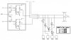
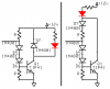
Ive got a mock up of the attached circuit on a breadboard...Ive substituted 2 LED's for the solenoids to see their operation. here is whats happening...I can remove the ground from the TIP41's emitter and the LED goes out. (got that part) I can add a ground to A, B, or off and the LED(s) go out. (easy enough) But why does the LED stay on when I remove the 12vdc from each half circuit? I would think that with the 12vdc gone, the base no longer gets any current and the ground between the emitter an collector would be open and the light would go out. Or is the ground going through D7 and around to ground? Is D7 even necessary? Could I remove it (D7) if I wanted to control the circuit by removing the 12vdc in this manner? Thanks for any info!!!
 

Attachments

  • gates solid state.jpg
    gates solid state.jpg
    97.2 KB · Views: 144
D7 arrests the very high voltage spike created by the inductance of the solenoid when it turns off.

When 12V is removed then Q1 is still turned on and the cathode of the LED has a voltage divided down to maybe 6V so there is current for the LED to light.
 

Attachments

  • circuit again.PNG
    circuit again.PNG
    23.6 KB · Views: 133
The LEDs are probably getting their ground path though D5,6&7 and the resistors when you remove the +12V. This wouldn't be a problem if the +12V on the right of the diagram is removed when the transistor +12V is removed.
You could remove D7 if you placed a diode directly across each of the solenoids. Actually, this would be the best anyway so that the circuit is protected from reverse EMF when SW1 is in "auto" mode.
 
I think your analysis is correct.
D7 is needed to protect the TIP41 from the flyback voltage that will be generated by the solenoid when its current is interrupted by turning off the transistor.
EDIT: Wow! Three answers within a 1 minute interval.
 
Status
Not open for further replies.

Latest threads

Back
Top