Continue to Site

Welcome to our site!

Electro Tech is an online community (with over 170,000 members) who enjoy talking about and building electronic circuits, projects and gadgets. To participate you need to register. Registration is free. Click here to register now.

  • Welcome to our site! Electro Tech is an online community (with over 170,000 members) who enjoy talking about and building electronic circuits, projects and gadgets. To participate you need to register. Registration is free. Click here to register now.

Chinese ultrasonic cleaner repair/modify

Status
Not open for further replies.

Mjolinor

New Member
Long first post, I am stuck with it at the moment.

I have some of these Chinese ultrasonic cleaners. They are well put together but they are obviously a 110 volt design. The Chinese thought they would make it suitable for 230 volt operation by removing 2 diodes in the bridge so that it only runs half the time.

That is fine in theory but in truth it doesn't work. These things blow up.

I can make them much better by changing the transistors from 400 volt to 1000 volt (BU508) but it does not fix the problem that the things take too much power and run way too hot. If they are run for 30 minutes then probably 80% will blow the transistors and diodes and trip the circuit breaker.

What I need to do is reduce the on time of the transistors I think. I have tried just about everything and am hoping to maybe get some inspiration from someone that is familiar with these "magic" oscillators.

I have tried:
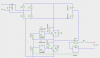
Turns ratio on feedback transformer both up to 2.5:18.5 and down to 2.5:5
Add base emitter resistor min 220 max 1k
Changed R1 and R2 to 100k to lower the base
Reduce and increase R3 and R4
Reduce and increase C1 and C2
Reduce and increase R5.1
Reduce and increase L5
Reduce C3 and C4

Nothing changes the way it runs. Instead of drawing 0.4 amps it draws about 1 amp. This is with 2 x 60 watt transducers in parallel.
The same circuit is used for one or two transducers, the only difference is that L5 is around 5 mH for one transducer and about 3 mH when it is driving two transducers. The 3 mH ferrite cored inductor is a lot bigger than the 5 mH one.

I am trying to avoid having to add either a whacking great resistor in the power leg or a 240/110 transformer, both those solutions are horrible.

I am quite sure that I can cure this by using a PIC micro to drive the bases of the transistors but an analogue solution would be neater and easier to implement.

Suggestions gratefully accepted.
 

Attachments

  • sch1.png
    sch1.png
    35.2 KB · Views: 2,068
Is core saturating? bad
Is transistor saturating < 0.5V? good
Analyze impedance of each part and check ratios of Ic/Ib
 
The transistors are both saturating. The 110/220 transformer is not saturating. The feedback transformer is saturating.

All as it should be I expect. The problem is the on time is too long for the supply voltage.
 
I am quite sure that I can cure this by using a PIC micro to drive the bases of the transistors
That might work, but the oscillator is a self-tuning type with a frequency determined partly by the transducer itself, so the micro would have to adapt for resonant frequency drift as a result of loading effects on the transducer. Could be tricky.
The feedback transformer is saturating. All as it should be I expect.
Why is feedback transformer saturation 'as it should be'? To get squared-off drive pulses for the transistor bases? I'm not well up on magnetics, but understand transformer saturation is normally something to be avoided.
I suspect the cause of the transistors frying is shoot-through. If the oscillations stop for any reason, both transistors are biased on via their collector-to-base resistors and conduct simultaneously.
 
If the oscillations stop then both transistors are biased off. 47k pull up versus 500 ohm pull down is definitely an off situation, L7 and L9 are only 13 turns on a one inch ferrite. This is only true for 110 volt supply, this is running from 230 so there is a possible problem.

On 110 we have 55 volts (static) on the top transistors emitter.
So
55*500/47500 = 0.58 volts
On 230 volt supply
115*500/47500 = 1.2 volts

Spot the difference. :)

Ferrite core saturation is useful for a lot of things, not least limiting the signal throughput which is (I suspect) the case here.
 
Last edited:
Hi Mjolinor,
Can you confirm my understanding of the circuit. L7,L8, and L9 are the windings on the feedback transformer. L1 and L2 are windings on the power transformer which match the half bridge output to the transducer. and L5 is just a choke. If these assumptions are correct then I suspect that the output transformer is saturating putting excessive load on the transistors. As the voltage output will be double what it was designed for I think you need to double the number of turns on the primary (L2) of the output transformer.

Les.
 
The circuit is drawn by me from the PCB so is not guaranteed :)

Your understanding is the same as mine but I suspect that the L1/L2 ferrite transformer is changed by the Chinese when they issue it as a 230 volt device as it is marked 220/110 and has a 2:1 inductance ratio. I do not know this for sure but I guess that ones shipped to the US have a 110/110 transformer there, I have never seen one so I don't know for sure.

Same thing basically and for 110 operation:
https://hackaday.io/project/4689-im...ineering-a-cheap-ebay-ultrasonic-power-supply

I just tried sticking a 470 in parallel with the 500 to lower the bias on the base and it seems a good result so far.
 
If the oscillations stop then both transistors are biased off. 47k pull up versus 500 ohm pull down is definitely an off situation
As you say, ok for 110V but you get shoot-through with 220V operation (at least, you do in a Spice sim).
On 230 volt supply
115*500/47500 = 1.2 volts
Its actually worse than that (if a transistor can die within half a mains cycle), since mains peak is ~320, not 230.
I just tried sticking a 470 in parallel with the 500 to lower the bias on the base and it seems a good result so far.
That should do the trick.
 
Tried this on a 1.3 litre, that is one board driving 1 transducer. Current flow is now 0.2 - 0.3 amps. This is good and no transistors getting hot.

So over to a 15 litre. This is 6 transducer, 360 watt driven from 3 identical boards. One board works fine drawing 0.5 - 0.6 amps. The second board does not oscillate at all, base bias too low to start it seems. The third board is still roasting itself and drawing 0.8 - 1.0 amps.

So, probably not a solution but possibly a good mod to fit to all of them.
 
I guess transistor beta differences account for the different current draws of the three 'identical' boards.
 
The only difference between the driving boards for the two transducer and the one transducer is the inductor in series with the transducer. For one transducer this is a ferrite transformer that measures about 5mH, for the two transducer it measures around 3 mH.

Any thought s on whether or not I can series the two transducers instead of parallel, that should reduce the power significantly if it oscillates correctly.

These things seem to oscillate pretty much randomly. I stuck the transducer in parallel between a sig gen and a scope and they resonate pretty much anywhere with very strong shorting of the signal at 40kHz, 56kHz, 74kHz, 102kHz 150kHz and a whole lot of smaller dips in between.

When running with their own board normally they actually seem to oscillate at around 96kHz.

Not a lot of sense attached to any of that really.
 
Any thought s on whether or not I can series the two transducers instead of parallel
I'd be (pleasantly) surprised if that worked. Since a piezo transducer is essentially a capacitor that would drop the capacitance by a factor of 4 and hence theoretically raise the oscillation frequency by the same factor. The reduced drive might not provide enough feedback to get the oscillations going.
Sounds like you didn't have the 3mH inductor in series with the transducer pair when doing those resonance checks? My guess is it would swamp any parasitic inductance which might have been responsible for the various non-harmonic resonances you detected.
 
I too would be happy.

More messing and 330 seems better but more importantly it is doing what we thought, taking less current the more I reduce that resistor up to the point where it does not start oscillating at all.

Even when paralled up these transducers take significantly different power. I can tell this from the temperature the transducer reaches when running, probably 20 or 30 degrees difference between the transducer temperatures, around 30 - 50 celsius.
 
Oh yes, and talking of them being a big capacitor I can vouch for this with the burns on my fingers, even after 24 hours they will have enough charge on for a serious head bang on the ceiling.
 
What sort of efficiency should I get with this circuit? I am measuring average current drawn, most other methods will upset the circuit it being self resonating.

I am sort of saying that with one 60 watt transducer I need to be 0.2 - 0.3 amps and with two then maybe 0.5 - 0.6 and I am taking 0.7 for one and over 1 for two as too much.

Is that reasonable?
 
Could the current difference between the three boards be due to inductor differences? For example, is the core material or inductance for L5 the same for all boards? And it doesn't take much for 2.5 turns on L8 to become 2.3 turns or 2.7 turns, which would affect the transistor base drive current.
What sort of efficiency should I get with this circuit?
I've no idea. How would you measure the ultrasonic power generated?
Is that reasonable?
It's not easy to calculate the current, since the waveform is far from sinusoidal.
 
There is need to calculate it, I can measure the average current flowing with an ammeter.

I know the transducers are 60 watt so I know what magnitude ish of power that should flow if I had any idea about the efficiency. Without any power dissipating devices in there with transistors saturating it should be a fairly efficient circuit I expect.
 
I can measure the average current flowing with an ammeter.
You mean RMS current from the mains? Does your meter read true RMS for weird waveforms?
Here's a sim showing transducer current waveform (I had to guess at transducer capacitance and coil inductances, so current value won't be accurate) :-
UltrasonicOsc.gif
.... and here are the mains voltage and current waveforms :-
VandI.gif

I know the transducers are 60 watt
That's presumably their maximum rating, rather than what you are actually getting?
 

Attachments

  • UltrasonicOsc.asc
    4.7 KB · Views: 413
Had I meant RMS I would have said RMS, as I meant average that is what I said.

These things are blowing transistors and transducers are exploding. Maybe I am being premature but I draw the conclusion that the transducers are being overdriven because if they were being asked to dissipate only 60 watts they would not be shattering and the transistors would not be getting hot.

If I could get the circuit to take only 60 watts per transducer then I would be happy because I am guessing again that if the circuit is drawing 60 watts then the transducer will probably be making at least 30 watts of ultrasonic assuming I do not mess too much with the filtering.

The circuit as supplied will run as sweet as a nut from 230 volts (DC) but over that and it starts getting distressed. It needs to run from 340 sweetly to be any use for mains operation in the UK.
 
Status
Not open for further replies.

New Articles From Microcontroller Tips

Back
Top