Continue to Site

Welcome to our site!

Electro Tech is an online community (with over 170,000 members) who enjoy talking about and building electronic circuits, projects and gadgets. To participate you need to register. Registration is free. Click here to register now.

  • Welcome to our site! Electro Tech is an online community (with over 170,000 members) who enjoy talking about and building electronic circuits, projects and gadgets. To participate you need to register. Registration is free. Click here to register now.

Chicken coop door control

Status
Not open for further replies.

perthdownunder

New Member
Hi all,

I am no good at electronics design, but I think I can follow a schematic and build a circuit and I'm even more confident that I can assemble a kit so I was hoping that someone could help me out with the design side of things.

I am building a chicken coop in our backyard partly for the eggs, partly for my kids and partly as another project to keep me busy. :)

What I am not really interested in is getting up at dawn to let the chickens out, especially as I'm a night owl and am often up to the small hours of the morning. I don't really mind shutting them in at night but figured if I could get a reversible door control it could shut itself at dusk and save me that trouble too.

I have found an existing controler that is available in England but buying and shipping it to Australia is going to cost over $200 and I don't think I can convince my wife to let me buy it. :(

What I would like to do is build a controler to control a DC motor which will raise and lower a vertical sliding door. Ideally, the door control will use a LDR to detect dawn and raise the door. The same LDR will detect when it is dusk and lower the door.

Bonuses to the design would allow a delay between 1-60 minutes between triggering the LDR and actually opening or closing the door as well as a mechanism that would operate like a garage door that would lift the door back up if it encounters an obsticle (like a chicken in the door), wait for a minute or two and then try to lower again. I'm not too worried about the last point though as I'll make sure that the door is light enough and moves slow enough that it won't hurt the chickens.

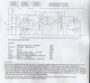
I was trying to see if there was some way to combine a couple of existing designs to get what I wanted. I was looking at LDR switch designs, timers and some of the reversible DC motor control designs. Some of the links in some of these forums have led me to kits which would maybe make it easier for me to assemble the final result if I can figure out how to combine them. Some of these are: https://www.electro-tech-online.com/custompdfs/2005/08/k79a.pdf, https://www.electro-tech-online.com/custompdfs/2005/08/k85.pdf and https://www.electro-tech-online.com/custompdfs/2005/08/k166-1.pdf

Can anyone help me out with this?

Thanks,
Graham
 
chicken door

sounds like an interesting under taking. if the chickens are for the kids i would make the kids get up with the chickens. but i am sure you have thougt of that already.

just an idear. take a light timer and plug into the opening motor. you can set it for dawn and dusk. at work we have laser sensors wired into the evacutaor doors. if something passes infrint of one of the sensors during a cycle then the doors will not operate. if you want i can get the name for ya.
 
I looked for a supplier in your location, but did not find any. These parts can be ordered from All Electronics. Schematic and explaination attached.
 

Attachments

  • solar_circuit.jpg
    solar_circuit.jpg
    139.2 KB · Views: 1,832
Hi Russlk,

Wow. Thanks for the diagram. I can follow how this works but just have a quick question about S1 and S2.

I assume that using these as limit switches I will need to rig the door up so that when it closes if will come to press down on the S1 lever which will open the switch and stop the door. Then in the morning when the motor reverses and lifts the door, the door lets S1 revert back to a closed position and similarly that when the door raises it will press S2 to an open position and then when it decends it will allow S2 to revert back to a closed position?

If this is how the switches work then while the door is moving between the fully open and fully closed positions (before hitting the limit switches in each direction) both S1 and S2 will be in a closed position?

The beauty of this design is also that it looks like the solar cells will slowly trickle charge the battery during the day. This means that the battery should last for ages without having to be replaced or recharged.

Thanks again,
Graham
 
Russlk said:
You are right, but when both switches are closed, only one relay is energized.

Thanks for all your help Russell. I'll let you know how I go.

I looked for some of the parts here today, but it is definitely not as easy to get hold of things in Australia as it is in the USA. I can get all the common parts like the resistors and the swtiches, but finding the geared motor and the solar cells is a bit more difficult (and/or more expensive than the USA). I have put in a query to allelectronics.com to see if they'll ship to Australia. If so I'll probably get most of the stuff from them.

Cheers,
Graham
 
Russlk said:
You are right, but when both switches are closed, only one relay is energized.

A couple of modifications that I have thought of for the design are a basic master switch on one side of the battery to allow me to turn off the door for maintenance or manual operation or things of that nature.

The other thing that I would like to do is incorporate a delay timer into the night side of the circuit. I have read a bit on 555 timers. Is this something that a 555 timer would be used for (eg. LM555 TIMER (MC1455))? Would it be terribly hard to incorporate a timer that waited say 1/2 and hour to an hour before the door closed after it got dark. This way the chickens would have plenty of time to get in and they wouldn't be left outside by mistake. The other thing that it could do is prevent unexpected door closures if say a really dark cloud went by as the delay would hopefully be enough for the light to come back and the circuit to reset itself to keep the door open. I'm not worried about the day side of the circuit as it isn't a problem to open the door as soon as there is enough light to trigger the photocell.

I have found a kit for a count-down timer (https://www.electro-tech-online.com/custompdfs/2005/08/ck1611.pdf) that uses a 555 oscillator and 4020 ripple counter to provide a configurable delay, but it is a 12vdc kit and I'm not sure what I might need to modify to make it suitable for the 6vdc door control. The kit controls a relay and I was thinking that maybe the components could be inserted into the door control circuit to control the night side relay instead of the kit relay. I could either build the kit on it's own PCB and then try to wire the two together or I could include the necessary components from that design onto the Perf Board that I build the door control on.

Can you recommend what to do about the voltage of the circuit, where to include the timer circuit in the door control circuit and whether you recommend incorporating the timer circuit into the door control or building the two separately?

Thank you in advance for your help with this.

Cheers,
Graham
 
Help with simpler project

Does anyone have a SIMPLE sircuit diagram for a circuit that can be used to operate a chicken coop door. It needs to open automatically in day light and close automatically at night. It has to run off less than 12V supply but I only need to make a model for a class I teach in school. :)

Many thanks
SSO:D
 
Hi Graham,

thinking about chicken and their behaviour I conclude you don't require a safety circuit to close the hatch.

The mechanical construction will be most decisive for the project.

If the door slides down slowly, driven by gravity it won't hurt a chicken. If it just passes underneath it will kneel down and slip through the opening.

The simplest way would be using some kind of reel pulling the door upwards and release it slowly when it has to be closed. If its weight is low enough chicken won't care either. They will stop the door by themselves if the gap becomes to small. (Don't attach a guillotine to the bottom edge of the door to give a following chicken a chance to survive. :D because of the sudden acelleration of the door.)

If one chicken stays outside the henhouse just press a remote button to reopen the door.

Chicken learn quickly and easily when they are expected to go home. None of them wants to miss its wooden bar to sleep. :)

Regards

Hans
 
Hello,
I'm sorry to post on this old post but I'm really interested by this project.
The problem is that it seems that the solar cell initially sold by allelectronics (cat# spl-07) is not available anymore.
Can someone give me the specification of this part to see if I can find it somewhere else? Or maybe a similar reference ?
Thanks in advance and sorry if my english is not perfect.
 
I don't like the photocell idea at all. I'd go for an astronominical timer. e.g. https://www.aliexpress.com/item/32989254010.html
Clouds and rain may cause the door to move when it's not supposed to.

These devices calculate sunrise and sunset. At home I have one that turns on a light 1 hour after dusk and off at 11:30 pm.

For DC operation thee might be some "smart relays" that have the timer function. Smart relays are mini-PLC's.

UP/DOWN motor control is loosely based on automotive power door controls using two automotive relays. One for up and one for down.
They are arranged such that the DC motor is dynamically braked so the motor stops quickly. The trick is finding a limit switch that can handle the relay current which, I think, is on the order of 200 mA.

If neither or both relays are engaged, motion stops. No power is used by the coils if the door is fully open or fully closed.

This https://support.industry.siemens.co...-8-astronomic-clock/184923?page=0&pageSize=10 post suggests that Siemens LOGO might have the astronomical timer. LOGO does have a free simulator.

Here I put together more a more comprehensive limits which would allow the monitoring of open/closed and moving.
 
The approach I like the most for this task is 'no controls'.
A solar panel feeding a matching hobby motor well above a sliding gate. A string wound on the motor shaft pulls the gate upwards to open.

Daylight turns the motor above the gate winding the string and rises the gate and keeps the motor pulling up even when fully open, stalling and starving the current maintaining torque.
At dusk, the motor cannot keep the gate up any more and it gets lowered closing the entrance by gate weight.
No limit switches, no LDR sensors, no timers, no circuitry, no external power supply, no nothing else...
Solar panel, string, weak motor, sliding vertical gate.
 
I agree with having a string pull it open, if it closes on an object then it just stops.

Mike.
 
Status
Not open for further replies.

Latest threads

Back
Top