Continue to Site

Welcome to our site!

Electro Tech is an online community (with over 170,000 members) who enjoy talking about and building electronic circuits, projects and gadgets. To participate you need to register. Registration is free. Click here to register now.

  • Welcome to our site! Electro Tech is an online community (with over 170,000 members) who enjoy talking about and building electronic circuits, projects and gadgets. To participate you need to register. Registration is free. Click here to register now.

Checking the schematic of 72x8 LED matrix

Status
Not open for further replies.
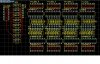
Can someone please check if i have put it all together correctly? I a trying to make PCB from this.

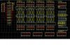
So i ll make 72x8 LED dot matrix display, and i thought of driving row by row. So refresh rate would be 1/8, and because of that i have put resistors to the anodes of rows which are very small value because if all 72LEDs are on, they would pull 0.5A. Doesnt mind those 10K on top of resistors, it is not true (i have calculated R should be 10ohms). Also doesnt mind those mosfets, i only know i have to use 0.5A, NPN transistors or something..
Columns are driven through 74hc595 and uln2803 to ground

On these pictures u will see only 2 8x8 matrices, but it would be 9 8x8

Please tell me if this would work the way i want (and think) it would :)

1.jpg
2.jpg
 
The shift register wiring looks OK to me. Assuming I didn't screw up the math, it looks like with your current setup you will need ~40 kilohertz shift clock to be able to refresh the entire screen 60 times a second, which is a very modest and easy to do speed. So I would say you have your overall design pretty well figured out.

If I changed anything about what you have now, I would put the resistors on every column, not every row, unless I was really trying to cut cost. Doing it your way puts 72 LED's on one resistor, which could cause you problems with brightness, power, heat production and so forth. Also 500ma transistors are not going to cut it for 72 LED's unless they are very very low power LED's. I would aim for 2 amps per transistor, and I would probably use MOSFET's, not BJT's. If you do the resistors like you have them now, make sure they are large, 5 watt or more units. And make sure they are fairly precise.

Another option is to buffer between columns after each 8 LED section. This would solve both the transistor and resistor problems simultaneously.
 
Ok, than i will put mosfet with 2A or more :)
And i will put resistors as you said, because you are probably right.
I am now drawing PCB so ill post it here. It is really complicated :D
 
Here is my PCB project for now, some wires are missing for now. It is for 64 columns, i have put 4*16 connectors in the middle of the board (i think that is pretty good idea)..

I will see if i could actually make this board because it would be my first one :)

3.jpg
 

Attachments

  • 3.jpg
    3.jpg
    640.9 KB · Views: 436
  • 3.jpg
    3.jpg
    636.4 KB · Views: 466
Last edited:
For high side switching MOSFET's, make sure you are using p-channel MOSFETs and make sure they have logic level gates. Here is a good choice I would think. https://www.digikey.com/product-detail/en/SPP15P10PL H/SPP15P10PL H-ND/2783608


Also note, all of pin 3 should be wired to the same positive supply, and all pin 1's should be wired to the shift register, and all pin 2's go to the rows of LED's. Finally, know that the MOSFETs will invert your signal. Logic 1 on a MOSFET turns it OFF, logic 0 turns it on. So to turn on one row at a time, make sure the last 8 bits you send are all 1's minus the row you are activating.
 
Hmhmhm. Yea you are right about that, and thank you for your advice, but i drew board for mosfets that have:
PIN1: to shift register (base)
PIN2: to +5V (all of them, source)
PIN3: to rows.
Can you think of one that has that configuration? Just because of wiring.. I am almost done with drawing the board, and tomorow i will make it
 
Can you think of one that has that configuration?

They probably do make them like that, but I have never seen them that way. 99.99% of all MOSFETS are in the pin order Gate/Drain/Source.

You are probably SOL on that front, sorry.
 
Ok then, i have corrected it :)
One more question. I have +5V on the other side of board, do i need it to be more than 10mils? Because of current i mean. All wires are 10mils for now
 
I have +5V on the other side of board, do i need it to be more than 10mils?

Probably for some things.

10mil traces on 2oz board can handle a max of ~1.5 amps. Some of the connections, the aggregate power traces mostly, could need more than that. I would say 15~20 mills would be best. PCB fab houses usually charge more for doing boards with thinner traces, as it takes better equipment and testing to do it, and it may require more etchant. So going bigger with the traces may have a price benefit.

This is (used to be) the cheapest small run PCB fab service I have found for large 2 sided boards with large traces.
**broken link removed**
 
I am almost done with it !
This is second i have made, first one didnt have some wires at all, no pads.. :D
On the second one there was only 1 wire that wasnt connected to all pads it should be, but it was easy to correct.
Also, i think it is much better to make one than to buy it. This board was 5$, and chemicals almost free. My friend tought me how to do it, and he have UV-leds.

So..here it is. I have made it like you said, with 64 resistors, but i bought this: https://www.futurlec.com/Transistors/IRF9630.shtml, and i tried it on breadabord and it works well. This board isnt complete, it is on 99% :)

But there is a lot of work to do to connect all those matrices the right way

IMG-20130425-WA0000.jpg
 
Nice work, can we get a picture of the back side maybe?

UV-LEDs? Did you actually go full out photo printing on your PCB? Most people doing PCB's in the home use toner transfer. I personally would like to go photo printing myself. I really need fine pitch traces for some of my planned projects, but the investment cost for a full high resolution photo PCB printing setup is to high for me. With the cost of good quality LASER printers staying really high, I'm probably going to be left only able to use breakout boards.

Anyway, moving on...

Now correct me if I'm wrong, but you are going to light one horizontal row at a time, starting at (for instance) the top, then going down to the bottom? Meaning one full screen refresh cycle will consist of 8 "steps", where each "step" turns on or off any number of 64 LED's for a set time? If so, then the way you have the setup now is perfect, and you should see consistent brightness across all LED's without having to resort to changing the duty-cycle based on how many LED's are lit.

If however you were lighting each column at a time, then you may run into significant differences in brightness depending on how many LED's you light up. This is because all LED's being lit in a column have to share current through the one resistor, but just one LED will git all the resistors current to it's self. If this was going to be an issue it would be an easy fix in software, one would just use a shorter on time for lighting single LED's. This may also require the use of the output enable pin on your shift registers though.

It's better to do one row at a time anyway, much much faster and more consistent and reliable LED performance.
 
I have posted you replay 3 times and i see now that something went wrong :(

Here is the picture of the back side before i started soldering it

I did the process of making PCB for the first (and second) time. First time it was not good, so i did it for the second time and at that time only 1 wire was broken. I did it with a help from a friend, he know the process and has chemicals and UV-LEDs.
So i have printed my 2 sides of PCB to plaus paper on a laser printer. Then I alligned those papers and put board between them. I put it in the some kind of box with LEDs on upper and lower side of PCB. Lightning was 7.5mins long, and then i put it into 2 chemicals for some time and that was it. Pretty easy i would say. I have just ordered 200 UV leds for myself :)

And, yes, i will turn on and of row by row, so the whole cycle would consist of 8 steps like you said :) I hope it would work

But today i run into a problem. I have completed my board, and i have programmed atmel328P in arduino uno and put it into my board. Just simple LED blink (pin 13). LED DID blink but just a few times. On original arduino this chip works well, led blinks, but on my board it blinks just few seconds, and then it looks like it run out of power. Like some capacitors is "eating" power. I pull current from USB so that is not a problem. Shift registarts dont work either. I dont know why is this (LED running our of power)..
 
But today i run into a problem. I have completed my board, and i have programmed atmel328P in arduino uno and put it into my board. Just simple LED blink (pin 13). LED DID blink but just a few times. On original arduino this chip works well, led blinks, but on my board it blinks just few seconds, and then it looks like it run out of power. Like some capacitors is "eating" power. I pull current from USB so that is not a problem. Shift registarts dont work either. I dont know why is this (LED running our of power)..

What power supply are you using? You may need something bigger. Try a PC power supply. Use the red and black wires.

Also, something I noticed the other day but forgot to mention, the FET's you are using are not specifically labeled logic level. Logic level FET's are made so they can be activated by things like shift registers and AVR micros. By not being specifically logic level FET's, they could be left slightly turned on and causing a system wide power drain, though this should also show up as all the LED's glowing a little bit. Try pulling the connections for all but one row of the LED's, this should limit any power draw from such things down to a minimum.

Also, did you remember that a logic 1 to a FET turns it off ??? Make sure you are sending ground/logic 0 to only the one you are turning on.
 
I understand why i should use bigger power supply but usb is not a problem if i am only powering arduino and 1 LED (not in matrix).
Also, i have tested this configuration on breadboard, but without arduino and programming shift registers, i have only put wires on +5V or 0 as logic 0 and 1 and it worked. As shift registar also gives only 5 or 0 i think it would be good.
And about turning on FET.. i wrote 170 which is 10101010 so 4 of them should be ON either way.
But it looks like that something is wrong with arduino connections because led on its pin 13 only blink for few seconds and then power "disapear"..
 
Last edited:
Status
Not open for further replies.

New Articles From Microcontroller Tips

Back
Top