Continue to Site

Welcome to our site!

Electro Tech is an online community (with over 170,000 members) who enjoy talking about and building electronic circuits, projects and gadgets. To participate you need to register. Registration is free. Click here to register now.

  • Welcome to our site! Electro Tech is an online community (with over 170,000 members) who enjoy talking about and building electronic circuits, projects and gadgets. To participate you need to register. Registration is free. Click here to register now.

Check my transformer spec?

Status
Not open for further replies.

antknee

New Member
Hi,

Could you check my transformer spec? I will build my first transformer with a kit from coilcraft and it is best to check i'm not barking up the wrong tree before i order!

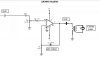
I have an audio amp the LM3886, that I'm using to drive a capacitor. The chip doesn't like capacitive loads so the transformer is isolating the capacitor. I'll be using it at high frequencies and the voltages tend to drop off at higher frequencies so I also need to step up the voltage.

Only two things are important:

Primary impedance = 8 ohms (the chip outputs this although it can output into 4)
Secondary inductance = 750uH (I require close to this, an LC resonant circuit with a 2nF capacitor must be set up)

Frequencies to be passed are 20KHz to 200KHz. The chip will output 200KHz at the gain of x30 i'm using, I've measured it with a scope so that isn't a problem.

So the calcs I've done are Primary inductance = primary impedance/ 2ΠFr = 8/(2Π x 20,000) = 63uH

So the transformer is 63uH:750uH or 1:3.4 turns

I'm thinking a toroidal air core because I need high frequency.

What size core am I going to need? How thick should the wire be?

Any thoughts welcome.
 
I assume this is for a piezo driver?

Please post a schematic.

The secondary coil will only resonate with the capacitive load at one frequency.

I suggest you avoid resonance because it will produce a very high voltage and current which will destroy the piezo.

An audio amplifier shouldn't have a probably driving a slightly capacitive load but there's probably a limit before it becomes unstable.

You might need to put an inductor in parallel with the piezo and tune it so it appears to be purely resistive, the problem is, it'll need adjusting every time you alter the frequency.
 
Hi Hero,

Yes it's a piezo driver.

lm3886-amp-circui-116-jpg.41254


I wasn't sure whether to use resonance with the piezo and secondary inductance or not. Perhaps its not a good idea.

I have just read the LM3886 datasheet again and it seems to prefer 4 ohms rather than 8 for output. It also states that ringing probably won't occur unless the capacitance is over 0.2uF, I'll not be going much over 2nF. So perhaps I won't need a transformer for isolation, more so possibly to get the voltage up.

I'd prefer not to have to tune with an inductor but I can try it.

I do have one question which is taxing me....

The 10uF capacitors on the input and output are elctrolytic and I'm not sure which terminal would be positive and which negative?

Cheers,

Antknee.
 

Attachments

  • LM3886 datasheet..pdf
    852.4 KB · Views: 247
  • LM3886 amp circui&#116.jpg
    LM3886 amp circui&#116.jpg
    20 KB · Views: 3,359
The amplifier will be fine as long as the load is greater than 4Ω.

The 10µF capacitors should be non-polarised.

The one on the output should be able to handle the current taken by the piezo, I'd recommend a metal film capacitor.

The transformer will reflect the capacitance of the piezo back to the amplfier, but something tells me it's not that simple because the transformer is inductive the capacitance will be cancelled by it. I think you should design it so the transformer's inductance isn't totally cancelled by the capacitance of the piezo and that the capacitance of the 10µF capacitor isn't totally cancelled by the transformer. To be honest, it's years since I did any of this so hopefully someone else here might know more about this than me.
 
Your schematic is not the same as the ones in the datasheet:
1) Your input capacitor is 10uF which has a cutoff frequency of only 1.6Hz into the 10k volume control. For a cutoff frequency of 8kHz so that 40kHz is not attenuated then the input capacitor can be a non-polarized 0.002uF ceramic one.
2) The Ri in your schematic should have a capacitor in series so that the amplifier does not amplify its input offset voltage. Then the output capacitor is not needed.
3) The Rf in your schematic should have a resistor in series to prevent the gain from being adjusted too low which will probably cause oscillation.
 
The 10uF capacitors are noted in the LM3886 datasheet as electrolytic. The single supply figure 2 diagram in the datasheet has a 10uF cap on the input with its positive terminal on the side of the amplifier. It seems to have a 470uF cap with its positive on the amplifier side. I'm thinking the positive of the caps should both be on the amplifier side.

The LM3886 came as a kit which I made up, it works very reliably. I added the 10uF caps to the schematic myself because they are required. The schematic i posted may not be completly accurate, it would be hard for me to say exactly what the difference is, because I don't know, but it works very well so its not worth worrying about.

I'm more interested in how to avoid problems with the transformer to be used with the amp. And how to make the transformer.

I'm thinking I should forget matching the piezo for a resonant LC circuit and simply step up the voltage by 10. I should probably keep the piezo inductive. I've heard that is what I'm supposed to do. Not sure why though!

What thickness of wire should I use? And what size core?

Cheers,

Antknee.
 
Last edited:
I have adjusted the spec based upon earlier comments. Thanks!

It would be better not to target an LC resonant circuit using the secondary inductance and piezo. I'm now going to look to step up the voltage by 11. The chip has a maximum power transfer with 4 ohms output so I'll also use that.

Using 4 ohms primary with a minimum frequency pass of 20KHz I need an inductance of 30uH.

With a voltage/turns step up of 11 the secondary inductance is 3.3mH (30uH x 121).

I wonder how big the transformer will be.

Does this spec look ok?

Thanks for your thoughts.
 
There is an inexpensive cleaning device being sold that uses an LM3886 amplifier driving a piezo transducer. Reviews of it say that it fails soon when its piezo transducer runs out of cleaning fluid. Maybe you should buy one to see how they did it.
 
Hi Audioguru.

I bought one, it stopped using the LM3886. It now uses the LM1875 which is cheaper I presume, so it wasn't that instructive. It also uses a frequency above which I want so the only useful thing I got out of it was the transformer. I did decide the transformer wouldn't work, but that was based on the wrong spec I posted originally, I will check it tomorrow, maybe it'd do and I don't have to make one. That'd be a result!

Cheers.
 
I'm thinking I should forget matching the piezo for a resonant LC circuit and simply step up the voltage by 10. I should probably keep the piezo inductive. I've heard that is what I'm supposed to do. Not sure why though!
That makes sense to me.

You don't want any resonance and the circuit needs to remain slightly inductive to keep the amplifier happy.

You can use the impedance matching formula or voltage boosting to deturmine the turns ration, depending on which is more convenient.

A turns ratio of 1:10 will divide the traducer's impedance by √10 = 3.16.
Impedance matching - Wikipedia, the free encyclopedia
 
Hi Hero,

Yes that is pretty much on the money. I have a few collected transformers to try tomorrow in the hope I get something close to what I need from them. I don't think I will so then it is buy some cores and wire. Should be fun! :)

Cheers.
 
Last edited:
Status
Not open for further replies.

Latest threads

New Articles From Microcontroller Tips

Back
Top