Electro Tech is an online community (with over 170,000 members) who enjoy talking about and building electronic circuits, projects and gadgets. To participate you need to register. Registration is free. Click here to register now.
Welcome to our site! Electro Tech is an online community (with over 170,000 members) who enjoy talking about and building electronic circuits, projects and gadgets. To participate you need to register. Registration is free. Click here to register now.
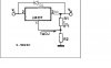
What i am trying to do is modify the existing circuit to charge NiMh batteries.the circuit below is what is currently on the pcb. R1=470ohm, R2=2000ohm and R3=2.2ohm and D1 = 2BL4. They are charging a 6v seal-lead acid battery and i want to replace this with 5x1.2V cells giving 6V.
hi mike,
As you not have said what the battery rating is, perhaps this will help.
Extract from a website...........................
How long will it take a charger to charge batteries?
It's pretty easy to estimate how long it will take. Simply divide the capacity of the battery by the charge rate of the charger, then increase the amount of time by about 20% to allow for a certain amount of inefficiency. As an example, a battery with a capacity of 1600 mAh will require about 4 hours to be fully charged by a charger with a charge rate of 500 mA. (1600 mAh/500 mA x120%). Incidentally, this example would apply to a standard AA NiMH battery and a typical "rapid charger". Keep in mind that a battery that is only partially discharged will be recharged in less time.
On this link they have an interactive charge calculator.
You can damage the battery by overcharging, they require an 'intelligent' type of charger, that monitors the battery charge state and adjusts the charge current/voltage to suit.
To answer your 'what voltage' , it depends upon the charge state of the battery.
Earlier I thought same like you… to design a simple charger for NIMH. But it’s hard to build a smart charger for NIMH as Eric said.
A simple circuit like 317 will work but always you have to concentrate on it whether it’s overcharging, whether it’s heating (the temperature), & charging time etc….
Simple charges there is no detection system like voltage, temperature, time…etc….
All smart charges design for NIMH has most of the functions included.
They are reducing the charging current after the battery is in charged condition. Trickle charging at a very low rate….this will improve NIMH batteries performance.
Will see how long you will use your NIMH batteries by charging with this simple charger.
Hi Eric,
the capacity of the cells is 900mAhr, they are used for a back up system should the 12V supply be cutoff. Did you have a look at the circuit i posted. Could i just place that "current resistor" into the circuit and remove the others as per the datasheet?
Had another look at the datasheet, the circuit you already have is OK as a battery charger.
Usually a 6V SLA [sealed lead acid] is trickle charged at a voltage of 6.8/6.9V and cyclic charged at 7.0V.
So it should charge the LiNM, but as Gayan points out, its not just the charge current when charging LiNM,
they require careful monitoring during charge to ensure that the current/voltage stay within their charge 'envelope'.
SLA are far more tolerant in their charging requirements.
I did check out the link, thanks. Nice one to save.
THe batteries i'm wanting to use are NiMh and they require a fixed current charge apposed to that of the SLA's which are fixed voltage chargers. The circuit as it is now gives out 6.6V but not sure what current. I need to supply around 100mA to trickle the new batteries however i dont think the existing circuit can charge at 100mA constant.
So i was wondering if i could just use that "one-resistor" current charger as in the datasheet. Place a 12ohm resistor by R3 and scrap the voltage divider circuit.
Checked, the 12R will limit the current to 104mA , as per your calc.
Do you have a 6.8V 1Watt zener in your scrap box?.
You could connect this across the battery terminal points from the charger.
If the charge voltage exceeds 6.8Vthe zener/battery it will start to sink the 104mA and hold the voltage to around 6.8V.
If you dont sink or clamp the voltage in some way, the current limit is going to try to drive 100mA into the battery, the voltage will keep rising until the battery fails.
It will work, but I still don't consider it a good idea, LiMH isnt very forgiving.
The attached circuit is closer to what you are looking for.
Remember to increase the value of R3 to reduce the current.
What you say akes sense. I saw that circuit in the datasheet - the only thing i am having trouble working out the resistor value for R3 to give me 100mA. Also i need a minimum of 7.2V to charge the 6v batteries, would adjusting the ration on R1 and R2 be suitable to bring this voltage up?
I looked at that equation but it doesnt work, cos they said that 1ohm gives 0.6A, so if you use the equation it doesnt give you that. Also i'm not worried about the input to the LM317 i need 7.2V or more on the OUTPUT to the cells.
Looked at page 18, current limit, only problem is no current cut off voltage limit.
I did post that, but had to revise, as the OP is charging LiMH batteries.
Hi mike,
The no load voltage of that circuit should be close to what you want, if not slightly increase R2.
It does work. It doesn't mention1 ohm or 0.6A so I don't know what you are looking at.
You don't need to worry about the output voltage - it will adjust itself to whatever it needs to be to maintain the constant current although as you say it does affect the voltage you need at the input which needs to be 2V or more higher than the output voltage.
This site uses cookies to help personalise content, tailor your experience and to keep you logged in if you register.
By continuing to use this site, you are consenting to our use of cookies.

 hm: at 0.6A = 0.6Vfwd.