Continue to Site

Welcome to our site!

Electro Tech is an online community (with over 170,000 members) who enjoy talking about and building electronic circuits, projects and gadgets. To participate you need to register. Registration is free. Click here to register now.

  • Welcome to our site! Electro Tech is an online community (with over 170,000 members) who enjoy talking about and building electronic circuits, projects and gadgets. To participate you need to register. Registration is free. Click here to register now.

Charge then discharge a capacitor

Status
Not open for further replies.

riccardo

Member
Hi, I want to set something up so that I can charge, and then immediately discharge a capacitor. With a relay, this would be simple, but I want to use transistors so I can do it at higher frequencies.

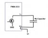
I have a couple of pulse generators (PWM-OCX) that can be linked together so that when one is on, the other is off, and visa-versa. I was thinking that I could set these up so that one charges the capacitor, then the other discharges it. The problem is that these circuit have an "open collector output". This means that the collector (source in this case as they are mosfets) is always grounded.

Is there some way I could modify these or add an extra transistor/diodes to do this?
 
I assuming one end of the capacitor is grounded?
 
No, I've attached a diagram showing my capacitor connected to the PWM. Basically, the PWM when high, connects the L- connector to ground and therefore charges the capacitor.
 

Attachments

  • ocx.jpg
    ocx.jpg
    10.9 KB · Views: 1,597
The PWM can only sink current; not source it. I think you are confused about the internal connections in your PWM modules. The internal NFET's source is tied to the ground terminal.

Here is my proposal:

You need to consider the peak currents through the FETs; they are HUGE.
 

Attachments

  • DF138.png
    DF138.png
    29.9 KB · Views: 172
Last edited:
Thank you, that looks great. Now one thing is that the charging voltage (V2) would be 1000V (I'm swapping out the installed mosfets). Can I just increase the value of R1 to 50k to accommodate this?
 
1000V???? What are you doing? Yet again, I have wasted my time coming up a proposal only to find that the OP has withheld critical information!

You will have a huge problem finding N and PFets that will work reliably at those voltages. Note that the high-side switch PFet will not tolerate a Gate to Source voltage of more than ~20V, so that configuration will not work. Look into an opto-isolator to drive the gate of the high-side switch.
 
Status
Not open for further replies.

Latest threads

New Articles From Microcontroller Tips

Back
Top