Electro Tech is an online community (with over 170,000 members) who enjoy talking about and building electronic circuits, projects and gadgets. To participate you need to register. Registration is free. Click here to register now.
Welcome to our site! Electro Tech is an online community (with over 170,000 members) who enjoy talking about and building electronic circuits, projects and gadgets. To participate you need to register. Registration is free. Click here to register now.
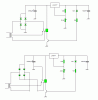
The first attachment is exactly the same as what I origionally posted.
The second is the same idea but it switches the negative line after the rectifier. You could switch the positive line after the rectifier, it doesn't matter.
You're right it's probably better to switch after the rectifier because the centre tapped point only has one rectifier voltage drop rather than two. The disadvantage is that most relays have a lower DC current rating than AC current rating so you might need a slightly larger relay.
Solid state deisgn is the best option as a transistor is cheaper and far more reliable than a relay. The disadvantage is that you need to allow for the saturation voltage of the transistor and that there will be two diode drops on the centre tap.
The current rating for a transformer is for the whole winding. If you use one half of the winding to the center tap, it still has the same current rating. The power output, of course, is one half.
I don't see that. A center tapped transformer is capably of the rated current, no matter which side of the coil is used (two windings in series). It's just the voltage dropping to 1/2.
The current rating for a transformer is for the whole winding. If you use one half of the winding to the center tap, it still has the same current rating. The power output, of course, is one half.
If you connect a bridge rectifier to a centre tapped transformer and connect a load from the +V or -V to the centre tap, both halves of the transformer's secondary will be used alternately.
Because the duty cycle through the secondary is now 50%, it's perfectly safe to exceed the current rating. The copper losses are equal to I²R so you can't safely double the current as this would quadruple the power dissipation. To get the same power dissipation you need to increase the current by √2, therefore the maximum current rating increases by √2.
Compare this bi-phase rectifier to a bridge with the load connected from the tap to the +V. **broken link removed** **broken link removed**
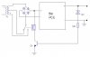
I've made circuit like this, but when the voltage gets more than 12V the relay starts clicking, and the voltage at the output is changing all the time...so anyone can help me...
btw the PSU is with lm723
There should be a diode in reverse parallel with the relay coil.
Another thing I've overlooked is that it could be oscillating because the filter capacitor is being discharged when the coil is activated causing the output voltage to drop slightly resulting in it being deactivated.
I can think of two solutions:
Add a capacitor from the transistor's base to 0V. This might help keep the transistor on for a long enough length of time for the relay to connect to the higher voltage tap.
Add a high value resistor (try 100k to 1M) from the + side of the rectifier to the transistor's base. This should add some hysteresis so when the relay does engage the transistor will turn on even more.
Failing that, are you sure the filter capacitor is large enough?
What's the secondary voltage of your trasformer?
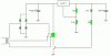
I would recommend using the solid state version: it should be much more reliable.
You might have to tweak a few component values, remember I haven't tested or simulated any of these circuits.
i have tryed all what you have posted, but i forgot to menton it in the prevous post....i will try the solid version tomorow or some other day when i will have time
Hero; your circuit is a very nice to reduce the regulator heat dissipation.
However, you do need to consider adding hysteresis to the switching transistor.
Otherwise, right at the voltage threshold, the circuit will start to misbehave between the two states.
The easiest, of course is to have an opamp with positive feedback.
But if you would like to maintain an all-discrete design, there is a two transistor design which has been designed eons ago. Lots of info by googling it.
The solid state version already has hysteresis built-in, there's no need to add an op-amp.
Positive feedback is accomplished by adding a 470k resistor from the collector of the PNP transistor top the base of the NPN transistor. When the NPN transistor turns on a bit, it will turn the PNP transistor on which will also apply a higher voltage to the base of the NPN transistor via the 470k resistor.
I didn't design any hysteresis into the relay version because relays already have some degree of hysteresis built-in. However I neglected the fact that because it breaks before makes it's prone to oscillation (as I mentioned above).
This site uses cookies to help personalise content, tailor your experience and to keep you logged in if you register.
By continuing to use this site, you are consenting to our use of cookies.

")