Continue to Site

Welcome to our site!

Electro Tech is an online community (with over 170,000 members) who enjoy talking about and building electronic circuits, projects and gadgets. To participate you need to register. Registration is free. Click here to register now.

  • Welcome to our site! Electro Tech is an online community (with over 170,000 members) who enjoy talking about and building electronic circuits, projects and gadgets. To participate you need to register. Registration is free. Click here to register now.

Change PWM Duty Cycle

Status
Not open for further replies.

drkidd22

Member
Hello,

I have a 60hz PWM signal which can change from two stages when a switch is fliped.
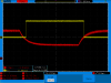
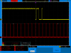
It changes from 5% duty cycle to 12.5% duty.

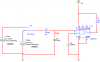
What I want to do is create a circuit that take the PWM as an input and that at 5% duty cycle my voltage is 0V and when at 12.5% duty cycle I want the full 5Vdc out. So basically make the 5% duty cycle a 0% duty cycle and the 12.5% duty cycle a 100% duty cycle.

I was thinking of using a differential op-amp maybe, but want to know if anyone here has any other suggestions.
 
How about a low- pass filter to integrate the PWM, then a comparator to switch to 100% when the critical voltage is passed.

John
 
Last edited:
Ok so I did a quick simulation in multisim and created the low pass filter with cut-off at 62Hz and using the lm311 comparator.
The only problem is that I'm not yet able to switch the output as I described before.

When V3Max is the + input to LM311, the voltage is 355mV and when V4Low is the + input to LM311 the voltage is 200mV.
I'm close to getting this working, but the output from LM311 doesn't witch from 0-5V output when I toggle the switch.
 

Attachments

  • freq.png
    freq.png
    16.3 KB · Views: 211
Last edited:
You could just use a Schmitt input gate as the threshold detector:-

Edit: Add another inverter to get the output polarity you specified.
 
Last edited:
Try a cutoff frequency of about 3 to 6 Hz. Here is a nifty calculator so you can see the response.

**broken link removed**
 
You could just use a Schmitt input gate as the threshold detector:-

Edit: Add another inverter to get the output polarity you specified.

Yeah that's what I want to do, specially with the Schmitt gate, but the requirements I have are a little different. I updated my circuit and just have to figure out the Schmitt thing out so that it trigger only as in your image but with my settings.
 

Attachments

  • freq.png
    freq.png
    14.2 KB · Views: 180
If I read your schematic correctly you only have 3.15 volts for the input signal. If that is true you may need to stay with the comparator. What you have now should work.
 
Yeah, What I have is only 3.15V. The circuit works ok in the sim, but there seems to be some jitter at the output for a few milliseconds before the output CMND complety changes stare. How can I get a smoother transition? I'm trying to get a smooth signal like alec_t posted on his wave form.
 
Last edited:
How can I get a smoother transition?
Try adding some positive feedback (3.3 meg?) from pin 7 to pin 2 of the comparator.
 
I simulated your circuit with added +ve feedback, but reliable jitter-free 2-way switching wasn't achievable. The jitter is due to the ripple on the waveform at the comparator input. The problem is that with simply smoothing the PWM signal (your circuit) instead of using a leaky rectifier (my circuit) the difference between the average voltage for the 5% and 12.5% PWM ratios is so small; less than the hysteresis provided by the feedback.
 
PWM Filter

The hysterisis needs to be larger than the ripple. So you need a lower frequency filter and more hysterisis. Try these values.
 
That helped a little, will do some more testeing at work tomorrow with the scioe and stuff.
 
Last edited:
The hysterisis needs to be larger than the ripple. So you need a lower frequency filter and more hysterisis. Try these values.

Thanks ronv, that did the trick. I'm not familiar with comparators, but this really helped be out. I found an LM393 and built the circuit. I will play around with inverting and non-inverting. You might have seen my other post need-help-switching-signals
it's related to this one.

I've attached an image of the results from my actual circuit.
I also added an image with feedback resistor removed.
 

Attachments

  • 20120125_775207.png
    20120125_775207.png
    28.3 KB · Views: 159
  • 20120125_780618.png
    20120125_780618.png
    33.4 KB · Views: 164
Last edited:
Cool. Is the long time constant ok for your purpose? It takes almost 1/2 second to make the step.
Is this for a plane or something else?
 
It's actually around where I need it, might need to play around with it when I'm a little more advanced on the project and during testing.
It for some crazy toy I'm working on. I got this RC car and an rc Airplane that I want to combine into one ;-). So it's help switching signals for air mode or plane mode using one of the toggle switchies of the transmitter.
 
Status
Not open for further replies.

Latest threads

New Articles From Microcontroller Tips

Back
Top